
The following circuit is part of a 555 timer diagram.
1 / 2
Title:
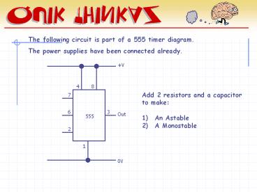
The following circuit is part of a 555 timer diagram.
Description:
The following circuit is part of a 555 timer diagram. The power supplies have been connected already. +V 4 8 Add 2 resistors and a capacitor to make: –
Number of Views:103
Avg rating:3.0/5.0
Title: The following circuit is part of a 555 timer diagram.
1
The following circuit is part of a 555 timer
diagram. The power supplies have been connected
already.
V
4
8
- Add 2 resistors and a capacitor
- to make
- An Astable
- A Monostable
7
3
6
Out
555
2
1
0V
2
ANSWERS
V
4
8
7
3
6
Out
555
2
Trig
1
0V
ASTABLE
Recommended
CrystalGraphics Presentations


