ASME P Material Numbers Explained - PowerPoint PPT Presentation
1 / 17
Title:
ASME P Material Numbers Explained
Description:
Gas Tungsten Arc Welding (TIG) GTAW Plasma Arc Welding PAW Straight polarity = Electrode -ve Reverse polarity = Electrode +ve – PowerPoint PPT presentation
Number of Views:151
Avg rating:3.0/5.0
Title: ASME P Material Numbers Explained
1
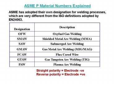
ASME P Material Numbers Explained ASME has
adopted their own designation for welding
processes, which are very different from the ISO
definitions adopted by EN24063.
Designation Description
OFW Oxyfuel Gas Welding
SMAW Shielded Metal Arc Welding (MMA)
SAW Submerged Arc Welding
GMAW Gas Metal Arc Welding (MIG/MAG)
FCAW Flux Cored Wire
GTAW Gas Tungsten Arc Welding (TIG)
PAW Plasma Arc Welding
Straight polarity Electrode -ve Reverse
polarity Electrode ve
2
ASME F Numbers
F Number General Description
1 Heavy rutile coated iron powder electrodes - A5.1 E7024
2 Most Rutile consumables such as - A5.1 E6013
3 Cellulosic electrodes such as - A5.1 E6011
4 Basic coated electrodes such as A5.1 E7016 and E7018
5 High alloy austenitic stainless steel and duplex - A5.4 E316L-16
6 Any steel solid or cored wire (with flux or metal)
2X Aluminium and its alloys
3X Copper and its alloys
4X Nickel alloys
5X Titanium
6X Zirconium
7X Hard Facing Overlay
Note- X represents any number 0 to 9
3
ASME A Numbers These refer to the chemical
analysis of the deposited weld and not the parent
material. They only apply to welding procedures
in steel materials.
A1 Plain unalloyed carbon manganese steels.
A2 to A4 Low alloy steels containing Moly and Chrome Moly
A8 Austenitic stainless steels such as type 316.
4
ASME Welding Positions Note the welding
progression, (vertically upwards or downwards),
must always be stated and it is an essential
variable for both procedures and performance
qualifications. Welding Positions For Groove
welds-
Welding Position Test Position ISO and EN
Flat 1G PA
Horizontal 2G PC
Vertical Upwards Progression 3G PF
Vertical Downwards Progression 3G PG
Overhead 4G PE
Pipe Fixed Horizontal 5G PF
Pipe Fixed _at_ 45 degrees Upwards 6G HL045
Pipe Fixed _at_ 45 degrees Downwards 6G JL045
5
G for Groove Welds F for Fillet Welds
6
- G
- for Groove Welds
- F
- for Fillet Welds
7
(No Transcript)
8
Welding Positions For Fillet welds-
Welding Position Test Position ISO and EN
Flat (Weld flat joint at 45 degrees) 1F PA
Horizontal 2F PB
Horizontal Rotated 2FR PB
Vertical Upwards Progression 3F PF
Vertical Downwards Progression 3F PG
Overhead 4F PD
Pipe Fixed Horizontal 5F PF
9
(No Transcript)
10
(No Transcript)
11
(No Transcript)
12
Multiple-pass layers.
Weld layer sequence
13
Welding Positions QW431.1 and QW461.2 Basically
there are three inclinations involved. Flat,
which includes from 0 to 15 degrees inclination
15 - 80 degrees inclination Vertical, 80 - 90
degrees For each of these inclinations the weld
can be rotated from the flat position to
Horizontal to overhead.
14
Effects of expansion and contraction
15
CONTROLLING DISTORTION
16
HEAT AFFECTED ZONE
17
(No Transcript)


