MESF593 Finite Element Methods - PowerPoint PPT Presentation
1 / 5
Title:
MESF593 Finite Element Methods
Description:
... or Excel format. You may submit a ppt, doc, xls ... and 2 quadratic ... Symbol Default Design Microsoft Equation 3.0 MESF593 Finite ... – PowerPoint PPT presentation
Number of Views:64
Avg rating:3.0/5.0
Title: MESF593 Finite Element Methods
1
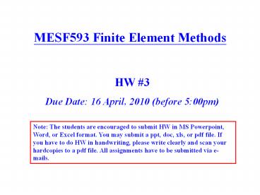
MESF593 Finite Element Methods
HW 3 Due Date 16 April, 2010 (before 500pm)
Note The students are encouraged to submit HW in
MS Powerpoint, Word, or Excel format. You may
submit a ppt, doc, xls, or pdf file. If you have
to do HW in handwriting, please write clearly and
scan your hardcopies to a pdf file. All
assignments have to be submitted via e-mails.
2
Prob. 1 (20)
P
(E, L)
Radius c
Radius 2c
Linear Model
Quadratic Model
A tapered bar with circular cross-section is
given as shown above. If two finite element
models (with 4 linear elements and 2 quadratic
elements, respectively) are used to simulate this
problem, compare the displacement results at each
node and the strain results in each element with
respect to the analytical exact solutions.
3
Prob. 2 (25)
Use the finite element method to solve for all
reaction forces and moment at the boundaries of
the beam given above.
4
Prob. 3 (30)
v4
A plane frame structure is given above. Plot the
deformed shape of the frame and find the value
(in terms of given symbols) of the vertical
deflection at the mid points indicated by the red
dots. (assume the axial deformation is
negligible i.e., use beam elements only)
5
Prob. 4 (25)
Po 100 MPa
Po 100 MPa
2b 200 mm
2a 400 mm
(Youngs modulus is E 200 GPa and Poisson Ratio
is n 0.3)
A unit thickness (1 mm) plate is given above. The
boundary and loading conditions are specified as
shown. Use four plane stress elements to find the
displacement of the corner node (marked in red).


