OUTLINE - PowerPoint PPT Presentation
Title: OUTLINE
1
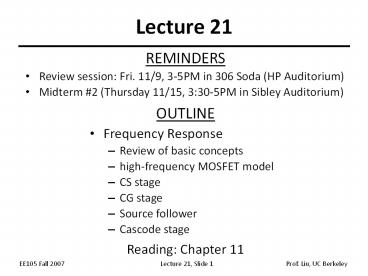
Lecture 21
- REMINDERS
- Review session Fri. 11/9, 3-5PM in 306 Soda (HP
Auditorium) - Midterm 2 (Thursday 11/15, 330-5PM in Sibley
Auditorium)
- OUTLINE
- Frequency Response
- Review of basic concepts
- high-frequency MOSFET model
- CS stage
- CG stage
- Source follower
- Cascode stage
- Reading Chapter 11
2
Av Roll-Off due to CL
- The impedance of CL decreases at high
frequencies, so that it shunts some of the output
current to ground. - In general, if node j in the signal path has a
small-signal resistance of Rj to ground and a
capacitance Cj to ground, then it contributes a
pole at frequency (RjCj)-1
3
Pole Identification Example 1
4
Pole Identification Example 2
5
Dealing with a Floating Capacitance
- Recall that a pole is computed by finding the
resistance and capacitance between a node and
(AC) GROUND. - It is not straightforward to compute the pole due
to CF in the circuit below, because neither of
its terminals is grounded.
6
Millers Theorem
- If Av is the voltage gain from node 1 to 2, then
a floating impedance ZF can be converted to two
grounded impedances Z1 and Z2
7
Miller Multiplication
- Applying Millers theorem, we can convert a
floating capacitance between the input and output
nodes of an amplifier into two grounded
capacitances. - The capacitance at the input node is larger than
the original floating capacitance.
8
Application of Millers Theorem
9
MOSFET Intrinsic Capacitances
- The MOSFET has intrinsic capacitances which
affect its - performance at high frequencies
- gate oxide capacitance between the gate and
channel, - overlap and fringing capacitances between the
gate and the source/drain regions, and - source-bulk drain-bulk junction capacitances
(CSB CDB).
10
High-Frequency MOSFET Model
- The gate oxide capacitance can be decomposed into
a capacitance between the gate and the source
(C1) and a capacitance between the gate and the
drain (C2). - In saturation, C1 ? (2/3)Cgate, and C2 ? 0.
- C1 in parallel with the source overlap/fringing
capacitance ? CGS - C2 in parallel with the drain overlap/fringing
capacitance ? CGD
11
Example
with MOSFET capacitances explicitly shown
Simplified circuit for high-frequency analysis
CS stage
12
Transit Frequency
- The transit or cut-off frequency, fT, is a
measure of the intrinsic speed of a transistor,
and is defined as the frequency where the current
gain falls to 1.
Conceptual set-up to measure fT
13
Small-Signal Model for CS Stage
14
Applying Millers Theorem
Note that wp,out gt wp,in
15
Direct Analysis of CS Stage
- Direct analysis yields slightly different pole
locations and an extra zero
16
I/O Impedances of CS Stage
17
CG Stage Pole Frequencies
CG stage with MOSFET capacitances shown
18
AC Analysis of Source Follower
- The transfer function of a source follower can be
obtained by direct AC analysis, similarly as for
the emitter follower (ref. Lecture 14, Slide 6)
19
Example
20
Source Follower Input Capacitance
- Recall that the voltage gain of a source follower
is
Follower stage with MOSFET capacitances shown
- CXY can be decomposed into CX and CY at the input
and output nodes, respectively
21
Example
22
Source Follower Output Impedance
- The output impedance of a source follower can be
obtained by direct AC analysis, similarly as for
the emitter follower (ref. Lecture 14, Slide 9)
23
Source Follower as Active Inductor
CASE 1 RG lt 1/gm
CASE 2 RG gt 1/gm
- A follower is typically used to lower the driving
impedance, i.e. RG is large compared to 1/gm, so
that the active inductor characteristic on the
right is usually observed.
24
Example
25
MOS Cascode Stage
- For a cascode stage, Miller multiplication is
smaller than in the CS stage.
26
Cascode Stage Pole Frequencies
Cascode stage with MOSFET capacitances
shown (Miller approximation applied)
27
Cascode Stage I/O Impedances


![[PDF] DOWNLOAD FREE Clinical Outline of Oral Pathology: Diagnosis and PowerPoint PPT Presentation](https://s3.amazonaws.com/images.powershow.com/10076578.th0.jpg?_=20240711025)


![[READ]⚡PDF✔ Black Letter Outline on Contracts (Black Letter Outlines) 5th Edition PowerPoint PPT Presentation](https://s3.amazonaws.com/images.powershow.com/10044064.th0.jpg?_=20240531080)


