Tail Escape
Title: Tail Escape
1
Tail Escape
2
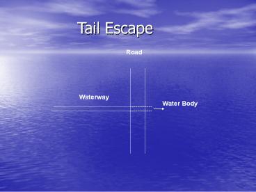
- Tail escape is a structure constructed at the end
of a waterway to evacuate the water to a water
body. - Tail escape consists of a well where its crest
level at the high water level. It is also
equipped with an orifice at its bottom to
evacuate all the water in 24 hrs if necessary. - A pipe evacuates the water to the water body
under the road.
3
Tail Escape
4
Hydraulic Design
- Hydraulic design of the tail escape consists of
three parts - 1. Automatic evacuation (Weir)
- 2. Controlled evacuation (Orifice)
- 3. Discharging to Sea (Pipe)
5
- Automatic Evacuation
- The excess water is evacuated over the weir's
crest. - The maximum acceptable rise in water level is 25
cm. - the discharge of water over the weir can be
calculated as follows - Qw Ts . h . Vs
6
- Where
- Qw is the weirs discharge in m3/sec,
- Ts is the top width of the water
- surface in m,
- h is the rise in water level 0.25 m,
- Vs is the surface water velocity in
- m/sec.
- Vs 1.17 vw
7
- Where vw is the mean water velocity of the water
way.
Ts
25 cm
H.W.L.
8
- To design the size of the well, the weir equation
is used, - Where
- Cd is the discharge coefficient 0.55,
- B is the crest length, and
9
- 2. Controlled Evacuation
- Orifice is designed to evacuate the waterway
in 24 hrs. The following equation is used to
determine the size of the orifice, - Where
- T is the time to empty the waterway
- 24 . 60 .60 sec
10
- L is the waterway length in m,
- be is the waterway average width in m,
- y is the depth of the waterway,
- Cd is the discharge coefficient 0.6
Ts
H.W.L.
be
y
b
11
- a is the area of the orifice in m2 and,
- Notice The orifice is equipped with a gate so
the water in the waterway can be used for any
purpose. The gate is open to evacuate the water
if needed.
12
- 3. Pipe
- The pipe is designed to the maximum discharge
for emergency as - Where
- Qp is the pipe discharge,
- Qo is the orifice discharge
13
- Where
- And,
- Where Vp is the pipe velocity (2.0 m/sec) and D
is the pipe diameter.
14
- Example
- A tail escape is required to be constructed at
the end of a waterway according to the following
data - Q 4.6 m3/sec, Waterway length 3000 m,
Vc0.45 m/sec
7.6 m
1.8 m
5.8 m
4 m
15
- Sol.
- a. Automatic evacuation
- Qw 7.6 0.15 (1.170.45)
- 0.6 m3/sec
- 0.6 (2/3)0.55B(v29.81)(0.15)1.5
- B 6.36 m
- D 2.7 m
- b. Controlled Evacuation
- T 246060
16
- a 0.2 m2
- do 0.5 m
- c. Pipe
- QpQwQo
- Qo0.60.2(v29.812.05)
- 0.76 m3/sec
- Qp 1.36 m3/sec
- Assume Vp 2 m/sec
17
- 1.36 2 Ap
- D 0.93 m take D 1.0 m
- Vp 1.73 m/sec


