Interpolation - PowerPoint PPT Presentation
Title:
Interpolation
Description:
Interpolation & Decimation For the ... are given by In matrix form we can write Polyphase Decomposition A multirate structural interpretation of the ... – PowerPoint PPT presentation
Number of Views:175
Avg rating:3.0/5.0
Title: Interpolation
1
Interpolation Decimation
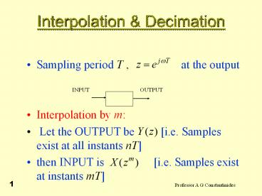
- Sampling period T , at the
output - Interpolation by m
- Let the OUTPUT be i.e. Samples exist at
all instants nT - then INPUT is i.e. Samples exist
at instants mT
2
Interpolation Decimation
- Let Digital Filter transfer function be then
- Hence is of the form i.e.
its impulse response exists at the instants mT. - Write
3
Interpolation Decimation
- Or
- Where
- So that
4
Interpolation Decimation
- Hence the structure may be realised as
INPUT
OUTPUT
Samples across here are phased by T secs. i.e.
they do not interact in the adder.
Can be replaced by a commutator switch.
5
Interpolation Decimation
- Hence
6
Interpolation Decimation
- Decimation by m
- Let Input be (i.e. Samples exist at
all instants nT) - Let Output be (i.e. Samples exist at
instants mT) - With digital filter transfer function
we have
7
Interpolation Decimation
- Set
- And
- Where in both expressions the subsequences are
constructed as earlier. Then
8
Interpolation Decimation
- Any products that have powers of less than
m do not contribute to , as this is
required to be a function of . - Therefore we retain the products
9
Interpolation Decimation
- The structure realising this is
Commutator
10
Interpolation Decimation
- For FIR filters why Downsample and then Upsample?
11
Interpolation Decimation
- A very useful FIR transfer function special case
is for N odd, symmetric - with additional constraints on to
be zero at the points shown in the figure.
12
Interpolation Decimation
- For the impulse response shown
- The amplitude response is then given
- In general
13
Interpolation Decimation
- Now consider
- Then
14
Interpolation Decimation
- Hence
- Also
- Or
- For a normalised response
15
Interpolation Decimation
- Thus
- The shifted response
- is useful
16
Design of Decimator and Interpolator
- Example Develop the specs suitable for the
design of a decimator to reduce the sampling rate
of a signal from 12 kHz to 400 Hz - The desired down-sampling factor is therefore M
30 as shown below
17
Multistage Design of Decimator and Interpolator
- Specifications for the decimation filter H(z) are
assumed to be as follows - , ,
,
18
Polyphase Decomposition
- The Decomposition
- Consider an arbitrary sequence xn with a
z-transform X(z) given by - We can rewrite X(z) as
- where
19
Polyphase Decomposition
- The subsequences are called the
polyphase components of the parent sequence
xn - The functions , given by the
z-transforms of , are called the
polyphase components of X(z)
20
Polyphase Decomposition
- The relation between the subsequences and
the original sequence xn are given by - In matrix form we can write
21
Polyphase Decomposition
- A multirate structural interpretation of the
polyphase decomposition is given below
22
Polyphase Decomposition
- The polyphase decomposition of an FIR transfer
function can be carried out by inspection - For example, consider a length-9 FIR transfer
function
23
Polyphase Decomposition
- Its 4-branch polyphase decomposition is given by
- where
24
Polyphase Decomposition
- The polyphase decomposition of an IIR transfer
function H(z) P(z)/D(z) is not that straight
forward - One way to arrive at an M-branch polyphase
decomposition of H(z) is to express it in the
form by multiplying P(z)
and D(z) with an appropriately chosen polynomial
and then apply an M-branch polyphase
decomposition to
25
Polyphase Decomposition
- Example - Consider
- To obtain a 2-band polyphase decomposition we
rewrite H(z) as - Therefore,
- where
26
Polyphase Decomposition
- The above approach increases the overall order
and complexity of H(z) - However, when used in certain multirate
structures, the approach may result in a more
computationally efficient structure - An alternative more attractive approach is
discussed in the following example
27
Polyphase Decomposition
- Example - Consider the transfer function of a
5-th order Butterworth lowpass filter with a 3-dB
cutoff frequency at 0.5p - It is easy to show that H(z) can be expressed as
28
Polyphase Decomposition
- Therefore H(z) can be expressed as
- where
29
Polyphase Decomposition
- In the above polyphase decomposition, branch
transfer functions are stable allpass
functions (proposed by Constantinides) - Moreover, the decomposition has not increased the
order of the overall transfer function H(z)
30
FIR Filter Structures Based on Polyphase
Decomposition
- We shall demonstrate later that a parallel
realization of an FIR transfer function H(z)
based on the polyphase decomposition can often
result in computationally efficient multirate
structures - Consider the M-branch Type I polyphase
decomposition of H(z)
31
FIR Filter Structures Based on Polyphase
Decomposition
- A direct realization of H(z) based on the Type I
polyphase decomposition is shown below
32
FIR Filter Structures Based on Polyphase
Decomposition
- The transpose of the Type I polyphase FIR filter
structure is indicated below


