OUTLINE - PowerPoint PPT Presentation
1 / 23
Title:
OUTLINE
Description:
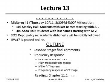
Lecture 13 ANNOUNCEMENTS Midterm #1 (Thursday 10/11, 3:30PM-5:00PM) location: 106 Stanley Hall: Students with last names starting with A-L 306 Soda Hall: Students ... – PowerPoint PPT presentation
Number of Views:65
Avg rating:3.0/5.0
Title: OUTLINE
1
Lecture 13
- ANNOUNCEMENTS
- Midterm 1 (Thursday 10/11, 330PM-500PM)
location - 106 Stanley Hall Students with last names
starting with A-L - 306 Soda Hall Students with last names starting
with M-Z - EECS Dept. policy re academic dishonesty will be
strictly followed! - HW7 is posted online.
- OUTLINE
- Cascode Stage final comments
- Frequency Response
- General considerations
- High-frequency BJT model
- Millers Theorem
- Frequency response of CE stage
- Reading Chapter 11.1-11.3
2
Cascoding Cascode?
- Recall that the output impedance seen looking
into the collector of a BJT can be boosted by as
much as a factor of b, by using a BJT for emitter
degeneration. - If an extra BJT is used in the cascode
configuration, the maximum output impedance
remains bro1.
3
Cascode Amplifier
- Recall that voltage gain of a cascode amplifier
is high, because Rout is high. - If the input is applied to the base of Q2 rather
than the base of Q1, however, the voltage gain is
not as high. - The resulting circuit is a CE amplifier with
emitter degeneration, which has lower Gm.
4
Review Sinusoidal Analysis
- Any voltage or current in a linear circuit with a
sinusoidal source is a sinusoid of the same
frequency (w). - We only need to keep track of the amplitude and
phase, when determining the response of a linear
circuit to a sinusoidal source. - Any time-varying signal can be expressed as a sum
of sinusoids of various frequencies (and phases). - ? Applying the principle of superposition
- The current or voltage response in a linear
circuit due to a time-varying input signal can be
calculated as the sum of the sinusoidal responses
for each sinusoidal component of the input signal.
5
High Frequency Roll-Off in Av
- Typically, an amplifier is designed to work over
a limited range of frequencies. - At high frequencies, the gain of an amplifier
decreases.
6
Av Roll-Off due to CL
- A capacitive load (CL) causes the gain to
decrease at high frequencies. - The impedance of CL decreases at high
frequencies, so that it shunts some of the output
current to ground.
7
Frequency Response of the CE Stage
- At low frequency, the capacitor is effectively an
open circuit, and Av vs. w is flat. At high
frequencies, the impedance of the capacitor
decreases and hence the gain decreases. The
breakpoint frequency is 1/(RCCL).
8
Amplifier Figure of Merit (FOM)
- The gain-bandwidth product is commonly used to
benchmark amplifiers. - We wish to maximize both the gain and the
bandwidth. - Power consumption is also an important attribute.
- We wish to minimize the power consumption.
Operation at low T, low VCC, and with small CL ?
superior FOM
9
Bode Plot
- The transfer function of a circuit can be written
in the general form - Rules for generating a Bode magnitude vs.
frequency plot - As w passes each zero frequency, the slope of
H(jw) increases by 20dB/dec. - As w passes each pole frequency, the slope of
H(jw) decreases by 20dB/dec.
A0 is the low-frequency gain wzj are zero
frequencies wpj are pole frequencies
10
Bode Plot Example
- This circuit has only one pole at ?p11/(RCCL)
the slope of Avdecreases from 0 to -20dB/dec at
?p1. - In general, if node j in the signal path has a
small-signal resistance of Rj to ground and a
capacitance Cj to ground, then it contributes a
pole at frequency (RjCj)-1
11
Pole Identification Example
12
High-Frequency BJT Model
- The BJT inherently has junction capacitances
which affect its performance at high frequencies. - Collector junction depletion capacitance, Cm
- Emitter junction depletion capacitance, Cje,
and also diffusion capacitance, Cb.
13
BJT High-Frequency Model (contd)
- In an integrated circuit, the BJTs are fabricated
in the surface region of a Si wafer substrate
another junction exists between the collector and
substrate, resulting in substrate junction
capacitance, CCS.
BJT cross-section
BJT small-signal model
14
Example BJT Capacitances
- The various junction capacitances within each BJT
are explicitly shown in the circuit diagram on
the right.
15
Transit Frequency, fT
- The transit or cut-off frequency, fT, is a
measure of the intrinsic speed of a transistor,
and is defined as the frequency where the current
gain falls to 1.
Conceptual set-up to measure fT
16
Dealing with a Floating Capacitance
- Recall that a pole is computed by finding the
resistance and capacitance between a node and
GROUND. - It is not straightforward to compute the pole due
to Cm1 in the circuit below, because neither of
its terminals is grounded.
17
Millers Theorem
- If Av is the voltage gain from node 1 to 2, then
a floating impedance ZF can be converted to two
grounded impedances Z1 and Z2
18
Miller Multiplication
- Applying Millers theorem, we can convert a
floating capacitance between the input and output
nodes of an amplifier into two grounded
capacitances. - The capacitance at the input node is larger than
the original floating capacitance.
19
Application of Millers Theorem
20
Small-Signal Model for CE Stage
21
Applying Millers Theorem
Note that wp,out gt wp,in
22
Direct Analysis of CE Stage
- Direct analysis yields slightly different pole
locations and an extra zero
23
Input Impedance of CE Stage


![[PDF] DOWNLOAD FREE Clinical Outline of Oral Pathology: Diagnosis and PowerPoint PPT Presentation](https://s3.amazonaws.com/images.powershow.com/10076578.th0.jpg?_=20240711025)


![[READ]⚡PDF✔ Black Letter Outline on Contracts (Black Letter Outlines) 5th Edition PowerPoint PPT Presentation](https://s3.amazonaws.com/images.powershow.com/10044064.th0.jpg?_=20240531080)


