Chaster 7 Review - PowerPoint PPT Presentation
Title:
Chaster 7 Review
Description:
Title: Chaster 7 Review Author: George Staab Last modified by: nasselman Created Date: 2/2/1997 8:27:54 PM Document presentation format: On-screen Show – PowerPoint PPT presentation
Number of Views:31
Avg rating:3.0/5.0
Title: Chaster 7 Review
1
Bölüm 7 Çubuk ve Kablolarda Kuvvetler
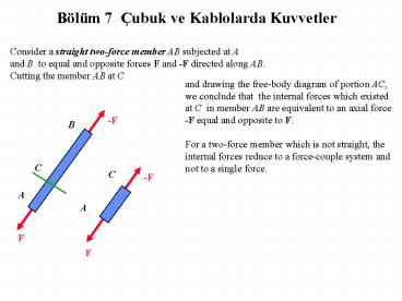
Consider a straight two-force member AB subjected
at A and B to equal and opposite forces F and
-F directed along AB. Cutting the member AB at C
and drawing the free-body diagram of portion AC,
we conclude that the internal forces which
existed at C in member AB are equivalent to an
axial force -F equal and opposite to F. For a
two-force member which is not straight, the
internal forces reduce to a force-couple system
and not to a single force.
-F
B
C
C
A
A
F
F
2
D
T
J
V
M
F
Considering multiforce member AD, cutting it at
J, and drawing the free-body diagram of portion
JD, we conclude that the internal forces at J
are equivalent to a force couple system
consisting of the axial force F, the shearing
force V, and a couple M.
3
D
D
T
T
The magnitude of the shearing force measures
the shear at point J, and the moment of the
couple is referred to as the bending moment at
J. Since an equal and opposite force-couple
system would have been obtained by considering
the free-body diagram of portion AJ, it is
necessary to specify which portion of member AD
was used when recording the answers.
V
J
J
C
Cx
M
F
Cy
FBE
B
Ax
A
Ay
4
Beams are usually long, straight prismatic
members designed to support loads applied at
various points along the member. In general, the
loads are perpendicular to the axis of the beam
and produce only shear and bending in the beam.
The loads may be either concentrated at specific
points, or distributed along the entire length
or a portion of the beam. The beam itself may be
supported in various ways. Since only
statically determinate beams are considered in
this text, we limit our analysis to that of
simply supported beams, overhanging beams, and
cantilevered beams.
5
To obtain the shear V and bending moment M at a
given point C of a beam, we first determine the
reactions at the supports by considering the
entire beam as a free body. We then cut the beam
at C and use the free-body diagram of one of the
two portions obtained in this fashion to
determine V and M.
C
C
6
M
M
V
V
The sign convention for positive shear force and
bending moment is as shown. Once the values of
shear and bending moment are established at
several select points along the beam, it is
usually possible to draw the shear diagram and
bending-moment diagram for the entire beam.
7
M
M
V
V
Constructing these diagrams is generally
facilitated by using the relationships
dM dx
dV dx
-w
V
Integrating these, we find
VD-VC -(area under the load curve between C and
D ) MD-MC area under the shear curve between C
and D
8
L
Ay
A
Ax
By
d
C1
D
Bx
C2
B
C3
P1
P2
x1
P3
x2
x3
For a flexible cable with negligible weight
supporting concentrated loads, and using the
entire cable AB as a free body, the three
available equations of equilibrium are not
sufficient to determine the four unknown
reactions at supports A and B.
9
L
Ay
Ax
A
Knowing the coordinates of point D, an additional
equation can be obtained by constructing the
free-body diagram of portions AD or DB of the
cable.
By
d
C1
D
C2
Bx
B
C3
P1
x1
P2
P3
x2
x3
Once the reactions are known, the elevation of
any point of the cable and the tension in any
section of the cable can be determined.
10
T
D
q
T
W
TO
C
q
TO
W
For a cable carrying a distributed load we
observe that the horizontal component of the
tension T at D is constant and must be equal to
the tension TO at C. The magnitude and
direction of T are obtained from the force
triangle.
W TO
T TO W 2
tan q
2
11
y
In a suspension bridge, the load is
uniformly distributed along the horizontal. The
load supported by portion CD of the cable is W
wx.
B
A
D(x,y)
C
x
w
The curve formed by the cable is a parabola of
equation
wx2 2To
y
12
y
For a cable hanging under its own weight, the
load is uniformly distributed along the cable
itself. The load supported by portion CD of the
cable is W ws.
B
D(x,y)
A
s
C
c
x
O
Choosing the origin O at a distance c To /w
below C , the relations between the geometry of
the cantenary and cable tension are
s c sinh y c cosh
y 2 - s 2 c 2
TO wc W ws
T wy


