IR Sensor for Line Follower
Title:
IR Sensor for Line Follower
Description:
IR Sensor for Line Follower Characteristic of IR sensor - The emitter transmits IR light - The receiver receives the reflected IR light IR Sensor for Line Follower ... –
Number of Views:228
Avg rating:3.0/5.0
Title: IR Sensor for Line Follower
1
IR Sensor for Line Follower
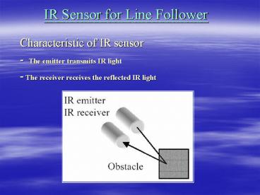
- Characteristic of IR sensor
- - The emitter transmits IR light
- - The receiver receives the reflected IR light
2
IR Sensor for Line Follower
- Characteristic of IR sensor
- - The current passing through the IR receiver is
proportional to the IR light energy intensity
received by it.
3
IR Sensor for Line Follower
- IR sensor circuit used in CEG3430 robot
- More intensity of reflected IR light received by
sensor, more voltage drop across the resistor in
series with sensor. - VR1 used to adjust the
- sensitivity of sensor circuit.
4
IR Sensor for Line Follower
- IR sensor circuit used in CEG3430 robot
- Modulated IR sensor circuit avoid interference by
the ambient light.
5
IR Sensor for Line Follower
- Differential IR sensor circuit proposed by Prof.
K.H. Lee - The basic idea of differential IR sensor circuit
is to compare two adjacent IR sensors output
value. - - Only the difference between adjacent sensors
value is used to detect the line.
v1gtv2 -gt high v1ltv2 -gt low
IR Emitter
v1
S2
S1
v2
-
Comparator
6
IR Sensor for Line Follower
- Differential IR sensor circuit proposed by Prof.
K.H. Lee - Advantages of using differential IR sensor
circuit - Independent of ambient light.
- Independent of floor material and color.
- Avoid interference by fluctuation of light
condition in surrounding environment. Such as
camera flash etc. - More reliable.
7
IR Sensor for Line Follower
- Design of Differential IR sensor circuit
- Define ?v v1-v2.
- If ?v gt 0.6 volt then line is detected.
- Else if ?v lt 0.6 volt then no line is detected.
Comparator
v1
-
If v1-v2 gt 0.6 volt then output - gt low
v20.6
v2
-
If v2-v1 gt 0.6 volt then output -gt low
v10.6
8
IR Sensor for Line Follower
- Design of Differential IR sensor circuit
- To achieve the previous rules, we have to use two
comparators. One for determine v1-v2 gt 0.6 volt,
another for determine v2-v1 gt 0.6 volt. - The circuit can be further modified as follow
Comparator
v1
-
If v1-v2 gt 0.6 volt then output - gt low
v20.6
v20.6
-
If v2-v1 gt 0.6 volt then output -gt low
v11.2
9
IR Sensor for Line Follower
- Implementation of Differential IR sensor circuit.
- The actual implemented circuit is as follow
VCC
VCC
Comparator
2K
10K
VCC
v1v2-0.6
s1
10K
s2
-
0.6 volt
LM339_1
Out
1N4148
v2v10.6
VCC
D1
-
D2
0.6 volt
10K
LM339_2
D3
v11.2
10
IR Sensor for Line Follower
- Implementation of Differential IR sensor circuit.
- Diode 1N4148 D1, D2 and D3 provide 1.2 volt
voltage difference between S1 output and negative
terminal of LM339_2 . - Initially, tune the 10K VR such that v1 lt v2 by
0.6 volt (both s1 and s2 sensors are at the same
condition). - The voltage value at different points of the
comparator should be as shown in the figure. - Pull up resistors must be added at the outputs of
LM339, because LM339 is an open collector output
device.
11
IR Sensor for Line Follower
- Differential IR sensor module circuit diagram.
12
IR Sensor for Line Follower
- References
- Diode 1N4148 datasheet
- http//download.siliconexpert.com/pdfs/diode/hit/
e208147_1n4148.pdf - Comparator LM339 data sheet http//www.onsemi.com
/pub/Collateral/LM339-D.PDF - OR gate 74LS32 data sheet
- http//ece-www.colorado.edu/mcclurel/dm74ls32.pd
f


