
PROFIBUS wiring/installation can be done with: - PowerPoint PPT Presentation
1 / 22
Title:
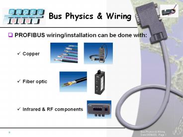
PROFIBUS wiring/installation can be done with:
Description:
Title: Parameterization Author: Current User Last modified by: 2 Created Date: 12/11/1997 4:06:10 PM Document presentation format: On-screen Show Other titles – PowerPoint PPT presentation
Number of Views:237
Avg rating:3.0/5.0
Title: PROFIBUS wiring/installation can be done with:
1
- PROFIBUS wiring/installation can be done with
- Copper
- Fiber optic
- Infrared RF components
2
- PROFIBUS is based on RS485...
3
- PROFIBUS Segments
4
- PROFIBUS Segments - Repeater
Segment 1
Segment 1
Isolation
Segment 2
5
- PROFIBUS - Segment Network Length
up to 9 in a row
6
- PROFIBUS Segments - Nodes/Devices
- Up to 126 addressable nodes per network
- Up to 32 devices per segment
- What counts as device?
! No PROFIBUS Address !
7
Up to 126 addressable nodes per network
- PROFIBUS Segments - Example
Address 0
Address 30
Address 31
Address 60
Up to 32 devices per segment
No Address
Address 90
Address 61
Address 120
Address 91
No Address
No Address
Address 121
Address 125
No Address
Repeater
OLM
8
- Installation
9
- Installation - Shielding Grounding
- Improves EMC behavior
- Provides a low impedance (short) return path for
noise and current - Reduces the emission from the bus
!!! Shield is not always connected to protective
GND within the devices therefore, make sure the
cable shield will be connected to GND before it
enters or leaves the cabinet !!!
10
- Installation - Cable Distances
gt 20 cm
Cable Category I
Cable Category III
Cable Category II
gt 10 cm
gt 10 cm
gt 50 cm
gt 50 cm
gt 50 cm
Cable Category IV
11
- Installation - Cable... (continued)
- Category I
- LAN cables (e.g. Ethernet)
- Other communication cables
- Category II
- Shielded and unshielded cables for DC voltages gt
60V and lt 400 V - Shielded and unshielded cables for AC voltages gt
25V and lt 400 V - Category III
- Shielded and unshielded cables for DC and AC
voltages gt 400 V - Category IV
- Signal cables of categories I - III at risk from
direct lightning strikes, e.g., connections
between components in different buildings
12
- Installation - T-Connections (Drop/Stub/Spur)
- Every branch or drop directly from the cable
- Stubs to devices cause reflections (additional
capacitance) - Repeaters are not spur-lines
Device
Device
RS485
RS485
! Manufacturer !
Internal to device Between device and trunk line
(A) (B)
13
- Installation - T-Connections (Drop/Stub/Spur)
For Drops above 187.5kBaud use Bus Terminals or
Repeaters
Although stub lines can theoretically be
tolerated at the lower baud rates, the
recommendation is to avoid the use of stub lines
altogether.
14
- Installation - Termination
- Termination for each segment at BOTH ends
- Termination works ONLY when supplied with power
Via Active Termination Box
Via Connector
Via integrated DIP Switches
15
- Installation - Termination Example
Repeater
OLM
OLM
OLM
16
- Wiring - Easy, when you use the right tools...
17
- Wiring - Easy, when you use the right tools...
3. Insert the end of the cable into the stripper
using your left index finger as a limit stop to
ensure the correct length is inserted.
1. How to hold the insulation stripper in your
right hand.
2. Match up the cable end with the template so
that your left index finger is against the end
surface of the tool.
6. With the clamp still closed, pull the stripper
off the end of the cable.
4. Clamp the cable firmly in the stripper.
5. Rotate the stripper around the cable 4 times
in the direction of the arrow.
18
- Wiring - Easy, when you use the right tools...
7. The removed insulation remains in the
stripper. After releasing the clamp, the remnants
can be removed.
8. Pull the protective foil off the cores.
9. After removing the insulation from the cores,
the cable can be fitted into the PB connector.
- green wire A
- red wire B
19
- Copper is not the End of the Road...
- Plastic, PCF and glass fiber optic available
- Plastic - 50m between 2 Optical Link Modules
(OLM) - PCF - 300m between 2 OLMs
- Glass - up to 15km between 2 OLMs
- Connections via modules or integrated interface
- When is Fiber Optic the Choice?
- Noise immunity independence from potential
differences - Cover longer distances
- Line, ring and star configuration possible
- Media redundancy
20
- Fiber Optic - Optical Link Modules (OLM)
PROFIBUS FO - Glass, PCF or Plastic
OLM
21
- Fiber Optic - Integrated FO Interface
PROFIBUS FO - PCF or Plastic
Optical Bus Terminal (OBT)
22
- More Options... Infrared Components
- Wireless linking of devices (up to 15m)
- Communication with moving devices
- Communication with changing devices
- Noise immune
- Ground independent
- More Options... RF Technology
- http//www.micro-control.no
- http//www.akerstroms.no
Recommended
CrystalGraphics Presentations


