LOGIC GATES - PowerPoint PPT Presentation
1 / 3
Title:
LOGIC GATES
Description:
LOGIC GATES Logic generally has only 2 states, ON or OFF, represented by 1 or 0. Logic gates react to inputs in certain ways. The AND gate will only switch on its ... – PowerPoint PPT presentation
Number of Views:381
Avg rating:3.0/5.0
Title: LOGIC GATES
1
LOGIC GATES
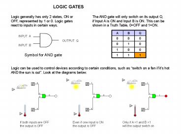
Logic generally has only 2 states, ON or OFF,
represented by 1 or 0. Logic gates react to
inputs in certain ways.
The AND gate will only switch on its output Q, if
Input A is ON and Input B is ON. This can be
shown in a Truth Table, 0OFF and 1ON.
A B Q
0 0 0
0 1 0
1 0 0
1 1 1
INPUT A
OUTPUT Q
INPUT B
Symbol for AND gate
Logic can be used to control devices according to
certain conditions, such as switch on a fan if
its hot AND the sun is out. Look at the
diagrams below.
If both inputs are OFF the output is OFF
Even if one input is ON the output is OFF
Only if A 1 and B 1 will the output switch on
2
MORE LOGIC GATES Try and work out the truth
tables for these gates. The rule will help you.
AND
A
Q
B
RULE Q 1 if A AND B 1
Q 1 if A OR B 1, but NOT both
RULE Q 1 if A OR B 1
A B Q
0 0
0 1
1 0
1 1
A B Q
0 0
0 1
1 0
1 1
A B Q
0 0
0 1
1 0
1 1
NOT
A
Q
RULE Q 0 if A OR B 1
RULE Q 0 if A AND B 1
RULE Q 0 if A 1
A B Q
0 0
0 1
1 0
1 1
A B Q
0 0
0 1
1 0
1 1
A Q
0
1
3
LOGIC GATES
AND
A
Q
B
RULE Q 1 if A AND B 1
RULE Q 1 if A OR B 1
Q 1 if A OR B 1, but NOT both
A B Q
0 0 0
0 1 1
1 0 1
1 1 1
A B Q
0 0 0
0 1 0
1 0 0
1 1 1
A B Q
0 0 0
0 1 1
1 0 1
1 1 0
NOT
A
Q
RULE Q 0 if A OR B 1
RULE Q 0 if A AND B 1
RULE Q 0 if A 1
A B Q
0 0 1
0 1 0
1 0 0
1 1 0
A B Q
0 0 1
0 1 1
1 0 1
1 1 0
A Q
0 1
1 0

