FPGA Implementation of the 3-D FDTD Algorithm - PowerPoint PPT Presentation
1 / 1
Title:
FPGA Implementation of the 3-D FDTD Algorithm
Description:
FPGA Implementation of the 3-D FDTD Algorithm This work was supported in part by CenSSIS, the Center for Subsurface Sensing and Imaging Systems, under the Engineering ... – PowerPoint PPT presentation
Number of Views:25
Avg rating:3.0/5.0
Title: FPGA Implementation of the 3-D FDTD Algorithm
1
FPGA Implementation of the 3-D FDTD Algorithm
This work was supported in part by CenSSIS, the
Center for Subsurface Sensing and Imaging
Systems, under the Engineering Research Centers
Program of the National Science Foundation (Award
Number EEC-9986821).
Wang Chen , Dr. Miriam Leeser , Dr. Carey
Rappaport wchen_at_ece.neu.edu
mel_at_ece.neu.edu
rappaport_at_ece.neu.edu
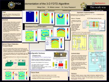
Hardware Implementation
Implementing the FDTD Algorithm in hardware will
greatly increase its computational speed and
widen its usage in many other areas.
Work in Progress
2D FDTD Model Hardware Structure
- Simplified and Quantized the 2D FDTD model as
first step. - Designed, simulated and synthesized modules for
Electrical field update, Magnetic field update,
Memory interface Boundary condition and Full
datapath.
The Quantized Fix-point Simulation
- Complete the 2D FDTD TE Wave model in hardware.
- Working on TM Wave model, with different
structure shown below.
Reconfigurable Hardware
Hardware design
- Figures above are the hardware structure of the
2D FDTD Free space model. The basic structure has
three parallel pipelines. Two pipelines are used
to update Electric Field, the other one is used
to update Magnetic Field. - We have 5 on-board memories and we use all of
them. Four memories are used for memory updating
and the last one is used to store the source
field value. - The detailed structure of electric field
pipeline module Exs is shown in the figure on the
right side.
Future Work
Reference
- Adding Different Soil and buried object
conditions to the 2D Model. - Testing and comparing the speed of 2D FDTD
hardware and software design. - Expanding the 2D FDTD model to 3D FDTD model.
1 Ryan N. Schneider, Laurence E. Turner, Michal
M.Okoniewski, Application of FPGA Technology to
Accelerate the Finite-Difference Time-Domain
(FDTD) Method, FPGA 2002. 2 Karl S. Kunz,
Raymond J. Luebbers, The Finite Difference Time
Domain Method for Electromagnetics, CRC Press,
1993."


