DIS SYSTEMS - PowerPoint PPT Presentation
1 / 16
Title:
DIS SYSTEMS
Description:
... the spark so it arrives as piston nearing TDC Adjusts spark timing with load & speed Electronic Ignition Systems Uses electronic ... tachometer signal Cylinder ... – PowerPoint PPT presentation
Number of Views:193
Avg rating:3.0/5.0
Title: DIS SYSTEMS
1
DIS SYSTEMS
2
Ignition Function
- Hot spark across spark plug gap
- Distributes high voltage to each plug in correct
sequence - Time the spark so it arrives as piston nearing
TDC - Adjusts spark timing with load speed
3
Electronic Ignition Systems
- Uses electronic control circuit to fire ignition
coil - More dependable than contact system
- Higher secondary ignition voltages
4
Magnetic Pickup Coil
- Produces tiny voltage pulses as magnetic field
changes - Trigger Wheel interrupts magnetic field
- Signals control unit to fire coil
5
Computer Controlled Ignition Systems
- Produce maximum engine power fuel efficiency,
reduced tailpipe emissions - Ignition spark timing is continuously and
accurately adjusted
6
Magnetic Pulse Generator
- Wire wrapped around a weak magnet, timing disk
mounted to the crank or cam shaft. Disk has
points or windows that interrupt the magnetic
field. AC voltage induced is sent to control
module to fire coil.
7
MP Generator Waveform
8
Hall-Effect Sensor
- Works similar to MPG
- Voltage generated at all times
- Rotating shutters interrupt the voltage, turning
off the voltage - Schmitt trigger cleans up the signal converts
it to a square wave (digital) signal
9
Crankshaft Sensor
(CKP)
Measures crankshaft RPM
10
Dual Crankshaft Sensor
Represents 1 cylinder
Represents each cylinder
- Two sensors in one
11
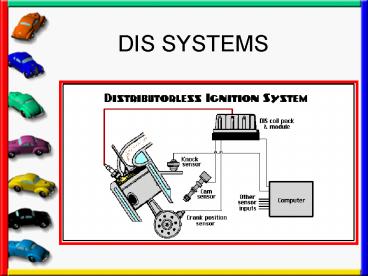
Distributorless Ignition Systems
- No Distributor
- One coil per two cylinders (waist spark)
- One coil per cylinder (coil over plug)
- Ignition Module synchronizes the firing sequence
in relation to crankshaft position - Ignition module signals ECM when to control each
fuel injector - Ignition module provides tachometer signal
12
Cylinder Arraignment
13
Waist Spark
- One coil per two cylinders
- 4
- Exhaust
- Stroke
- 1
- Comp.
- Stroke
14
Coil Over Plug
15
GMs C3 Ignition System
Ignition Control Module
16
Knock Sensor
- Mounted in engine block
- Detects preignition and detonation
- Vibrations create a small AC voltage which is
sent to ignition module or ECM - Computer determines if voltages are frequent
enough, if so, timing is retarded

