
Today - PowerPoint PPT Presentation
1 / 70
Title: Today
1
_README_ RF System Design Verification
(agenda, etc) for Ga Tech.doc ---Assignment
(directory) DP2_Assignment_2005.doc
DP2_Assignment_presentation.pdf ---RF System
Design and Verification (directory)
budget_analysis_app_guide.deb online
manual for RF Budget Analysis simulator.url
online manual for RF System DesignGuide.url
overview of ads2004a rf budget.pdf RF
Budget Analysis webpage.url RF System
design and verification.ppt
RF_Budget_Analysis (2004A, details).ppt
RF_Budget_Analysis (2004A, overview).ppt ---UWB
(directory) UWB_in_ADS2003C.ppt
UWB_update_for_ADS2004A.ppt
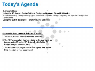
Todays Agenda
500 pm-700pm Using the RF System DesignGuide to
Design and Analyze TX and RX Blocks (extra
reference) Using Ptolemy (and standard-compliant
design libraries) for System Design and
Verification Using the DVB-H Examples brief
overview and demo
- Comments about material that I am providing
- The README doc contains the main overview.
- The PDF presentation files have training-like
overviews for the relevant ADS topics (RF System
DesignGuide, RF Budget Analysis simulator, etc.) - The archived ADS project should help a great deal
for the DVB-H portion of your assignment!
2
RF System Design and Verification using ADS
Tool RF System DesignGuide Used for RF System
Design Analysis in ADS Tool Ptolemy (and
standard-compliant Design Libraries) Used for
Design Verification of Real World Wireless
Systems (RF Mixed-signal Systems)
3
Before We Begin
A review of additional resources
4
Where else can you get help? Agilent EEsof EDA
Web SiteProvides access to Applications, Product
Support
- Application Information
- Product Information
- Download Online
- Examples
- Seminars
- Training
- App Notes
- Papers/Articles
- Updates/add-ons
- Documentation
- 24/7/365 Online access to technical support data
http//www.agilent.com/find/eesof
5
Where else can you get help? DocumentationProvid
es access to Manuals, Example Overviews, Search
Feature more
- Access through Help menu in any ADS window
- OR access by pressing F1 key in any ADS window
- OR access through Start?programs?Advanced Design
System 2003A?ADS Documentation
6
Where else can you get help? DocumentationSee
Documentation for RF System and UWB DesignGuides
- Once in ADS documentation, click on DesignGuides
- Scroll down to the bottom, and you will see this
window - Click on RF System to see more information on
this DesignGuide
7
Where else can you get help? Technical Support
- eesof_support_at_agilent.com
ADS Support Webpage http//www.agilent.com/find/e
esof-support See the NEW Knowledge Center
at http//www.agilent.com/find/eesof-knowledgecen
ter Latest ADS examples and applications http//
www.agilent.com/find/eesof-apps
8
Summary of Helpful Webpages for RF System Design
using ADS
RF System DesignGuide http//eesof.tm.agilent.com
/products/e5600a_rfsystem.html
Main ADS Webpage ADS Support
Webpage http//www.agilent.com/find/eesof
http//www.agilent.com/find/eesof-support Lates
t ADS examples and applications See the NEW
Knowledge Center at http//www.agilent.com/find/e
esof-apps http//www.agilent.com/find/eesof-knowl
edgecenter
9
Ease-of-Design Features
Templates
Design Guides
Examples
10
Ease-of-Design Topics
- Standard examples
- Templates What they are and how they help
- Application Specific Ease-of-Design Features
- RF System DesignGuide is one example
- Topic already covered in previous session
- Smart Simulation Wizard
11
Standard Examples Search for what you need
12
Standard ExamplesSeveral System-level and
Budget Analysis Examples
13
Ease of Design DesignGuides
- ADS DesignGuides
- Design expertise
- Tool expertise
- Makes better use of ADS capabilities
- Enables more complete testing
- Convenience
Immediate Productivity
Amplifier DesignGuide
Mixer DesignGuide
Passive Circuit/Filter DesignGuides
RF System DesignGuide
Bluetooth
CDMA2000
WLAN
UWB
PLL DesignGuide
Oscillator DesignGuide
Linearizer DesignGuide
14
RF System DesignGuideFeatures
- Over 180 Pre-configured Schematics and 200 Data
Displays - Configurable up and down converters (for
RF/Analog and for co-simulation) - Budget Measurements
- CNR, C/IMD, ACPR, EVM, Gain Compression, Spurious
Response, Linear parameters, Cascaded Gain, Power
and Noise Figure. - Modulation Sources
- QPSK, Pi/4 DQPSK, IS95, CDMA2000, 16,64 and 256
QAM (expandable) - Communication Examples
- GSM, OFDM, Bluetooth, 16 QAM
15
RF System DesignGuideMenu
16
RF System DesignGuideRF System Tests and Basic
Mod Types
RF System schematic configuration UI
System
Budget Measurements
Digital Modulation Sources
Topology
17
RF System DesignGuideTransmitter/Receiver
Topologies
- 8 Hierarchical Up/Down Converter Schematics
- - Define System Level components
- - Edit Configuration
- - Ready for use in Analog/RF simulations
18
RF System DesignGuideCo-Simulation Topologies
- 8 Co-simulation subcircuits
- - Configured with Circuit Envelope
- - Subnetwork ready for use in Ptolemy
19
RF System DesignGuideHierarchical Design
Circuit Level Amplifier
- Use a combination of Behavioral models and
Circuit Level models - Leave as Behavioral models or substitute with
your designs as you complete them
Distributed Filter
20
RF System DesignGuideCommunication Examples
- Communication Examples
- 16 QAM System, GSM Systems
- GSM Receiver, OFDM Transmitter, Bluetooth
Receiver
21
RF System DesignGuideDocumentation
22
RF System DesignGuide
Budget Measurement - CNR Data Display
Cascaded Performance along Chain
Phase Noise at IF Output
23
RF System DesignGuide
Budget Measurement - Inter-modulation Distortion
Data Display
3rd Order Intercept Point Curves
Node Carrier to IMD Curves
24
RF System DesignGuide
Constellation and Trajectory
Pi/4 DQPSK Data Display
Input Output ACPR
Pout Peak/Avg Power
Spectral Response
25
RF System DesignGuide20 New Analog/RF Digital
Modulated Sources
26
RF System DesignGuide Typical Source Top Level
and Subnetworks
Enables initial design verification to be
performed using Circuit Envelope Co-simulation
is not needed for basic measurements. Use Design
Library with Co-simulation to model Receivers,
measure BER/FER/PER, etc.
IQ Modulator
FDD with Expressions
- Check the effect of mismatch and compression on a
digital modulated signal directly in the analog
environment.
27
RF System DesignGuide Example Modulated Source
Top-Level 802.11a Burst Mode Source
28
RF System DesignGuide 802.11a Burst Mode Source
Subnet, IQ Mod
29
RF System DesignGuide Push Into IQ Mod Subnet
FDD with Expressions
30
RF System DesignGuide Typical Measurements
Signal Statistics
31
RF System DesignGuide Additional Measurements
Example, cdma2000 SR3 Source
ACPR
Trajectory and Constellation displays enabled by
13 new AEL expressions created for the RF System
DesignGuide
32
RF System DesignGuide Clock Offsets may be
varied in Data Display, no need to re-simulate
Clock Offset sets the phase of the symbol
clock. Path Offset offsets the receive clock from
the reference clock.
33
RF System DesignGuide Compare to Ptolemy Design
Libraries
34
Summary Benefits and Scope
- The RF System DesignGuide with standard-specific
Analog/RF Sources enables preliminary
verification of candidate circuit designs - Partially-coded, pre-set but statistically
correct signal sources are available within
Circuit Envelope, plus several transmit-oriented
measurements - Fully-coded and configurable sources, receiver
and demodulator topologies and bits-to-bits
measurements (BER, Sensitivity, etc.) require
Ptolemy Design Libraries and co-simulation
35
- Communications System Design and Verification For
RF Mixed Signal Applications (using Ptolemy)
- Application of ADS for Communications System
Architecture Development - Ease-of-Design Features
- RF Mixed Signal Simulation Technologies
- Integration of 3rd Party Simulators (Matlab ,
C, HDL) - Links to Test Equipment (Predefined links and VEE)
This is extra background material for those who
wish to learn more about the Mixed Signal (DSP
with A/RF) capabilities in ADS.
36
ADS is a Vertically Integrated Design Environment
System Architect
BER, Eb/N0, EVM
Baseband
RF Front End
ACPR, CNR, Phase Noise
RF sub-System Designer
Spurs
RF Circuit Designer
Coupler
EM Designer
Coupling
37
Ptolemy System Design Back Plane Tool
Matlab
C
RTL-HDL Designs
ADS Simulation Kernel
Connected Solution
Ptolemy Circuit Envelope Transient
ESG Sig Gen Vector Signal Analysis Spectrum
Analysis
RFIC Designs
Floating Point Fixed Point
RF uW Designs
Foundry Design Kits Links to Cadence
2G/3G Libraries 802.11a/b Library Xilinx Core Gen
Layout EM Design
38
ADS System Design Verification Flow
RX Sub-System
Analyze real signals from simulation data
Synthesize real signals from simulation data
RF/Analog Behavioral Models
Floating/Fixed Point Behavioral Models
Ptolemy SDF TSDF RTL
MATLAB
Transient Harmonic Balance Circuit
Envelope Cadence Link
Transistor-level
RTL HDL
Results
39
Integrated environment for RF/Analog Circuit
Simulation and Analysis
- AC/S-parameter (freq-domain)
- Low-power amplifiers
- Low-noise amplifiers
- Matching networks
- Noise matching
- Circuit Envelope (modulation-domain)
- Circuit and subsystem analysis with digitally
modulated RF signals (GSM, CDMA, W-CDMA) - PLL analysis
- AGC settling time
- Adjacent Channel Power Ratio
- Noise Power Ratio
- Oscillator start-up
- Pulsed RF response
- Harmonic Balance (freq-domain)
- System-level simulation
- Mixer intermodulation analysis
- Power amplifiers
- Frequency multipliers
- Oscillators
- Nonlinear noise (mixer NF, oscillator phase noise)
- HF Spice/Convolution (time-domain)
- Startup transients
- Oscillators
- Quasi-static nonlinear behavior
- Ptolemy Data Flow (discrete numeric/time-domain)
- Signal Processing Verification FEC,
Encoding/Decoding - System Performance Verification - BER
- Modulation Performance Verification EVM, ACPR,
CCDF
40
What is Agilent Ptolemy?
- System Level, Behavioral Simulation Kernel
- Timed and un-Timed Numeric simulation domains
- Links to other Simulators Instruments via
Backplane
41
Agilent Ptolemy
- Major Benefits
- Find the best design topology using
state-of-the-art technology with over 500
behavioral DSP and communication systems models - Provides technology standard compliant Design
Libraries - Co-simulate with RF and analog simulators
- Integrate your intellectual property from
previous designs - Reduce the time-to-market for your products
- Major Features
- Timed Synchronous Dataflow simulation
- Co-simulation capability with RF and analog
simulators - Easy-to-use interface for adding and sharing your
own custom models - Interface to test instruments
- Data Display with post-processing capability
- Integration with ADS DSP Synthesis
42
System Design using Ptolemy starting at the top
System Design
Partition Specifications
Detailed Design
Layout (Fabrication)
- Simulate system using behavioral models,
including RF and BB processing (FEC, Rate
Matching, Filtering) TAKE ADVANTAGE OF DESIGN
LIBRARIES! - Design system tradeoffs, coded versus un-coded
BER - Establish RX NF, Gain, etc.
Verification (Model Improvement)
43
RF System Model Library (SML)
- Provides Analog/RF Simulation of Block Behavior,
i.e. Mixer, PA, Filters, Modulators, PLL - Supports all Analysis Modes (HB, Tran, SP, CE)
- Model extraction from Circuit to Block
- Data Based Modeling
- Equation Based Behavioral Modeling
44
Budget Analysis
Allows user to see performance degradation at
every element in the system
Budget expressions are available as MsrEqn and in
the data display window
Expression Returns Budget Simulator bud_freq S
imulation frequency AC/ Harmonic
Balance bud_gain Transducer pwr gain AC/
Harmonic Balance bud_gain_comp Gain
compression Harmonic Balance bud_gamma Reflectio
n coefficient AC/ Harmonic Balance bud_ip3_deg IP
3 degradation Harmonic Balance bud_nf Noise
figure AC bud_nf_deg Noise figure
degradation AC bud_noise_pwr Noise Power AC/
Harmonic Balance bud_pwr Signal Power AC/
Harmonic Balance bud_pwr_inc Incident power AC/
Harmonic Balance bud_pwr_refl Reflected
power AC/ Harmonic Balance bud_snr Signal-to-n
oise ratio AC/ Harmonic Balance bud_tn Equivalen
t output noise temp AC bud_vswr Voltage standing
wave ratio AC/ Harmonic Balance
45
Breaking Out Blocks into Detailed Circuit Design
- Create Hierarchical Behavioral Designs
- Mix and Match Circuit and Behavioral Blocks
- Perform NF, Gain, IP3 budget calculations
Distributed Filter
Circuit Level Amplifier
46
Modeling Physical Effects of Design Detail
- Focus on Design Detail Including Layout Effects
- Conduct EM Simulation to extract performance and
parasitics
System Design
Partition Specifications
Detailed Design
Layout (Fabrication)
Verification (Model Improvement)
Distributed Filter
47
Solve new classes of board/module problems with
ADS Momentum
- Momentum/Momentum RF
- Complex PCB Trace coupling
- Signal contamination
- Interconnects
- Filters, couplers, arbitrary shapes
- BGA, SMT package modeling
- LTCC
- Antennas
Planar Antenna
96 PIN BGA
Signal Contamination
96 pin BGA
48
Co-simulation w/ Layout ComponentsBreaking Down
Barriers Between Electrical Physical domains
- EM/Circuit co-simulation from the schematic
environment - Transparent integration of electromagnetic
simulators at the schematic design level - Include physical layout parasitics in schematic
- Momentum simulation options accessible from
schematic - Compiled Layout Components listed in projects
hierarchy - Model database for reuse option
- Co-optimization is included
Momentum Component Generation
49
RF System Model Verification
- Incorporate RF circuit and SML components into
Ptolemy system simulation - Retains circuit-level fidelity in system design
context
50
Broad range of RF Behavioral Models for Superior
System Analysis
- Availability of a broad set of highly accurate RF
Behavioral SML Models. Users no longer have to
create the models themselves. - Easier to use Behavioral Modeling Language
capability (UCM, SDDs, FDDs). - New Automated RF Behavioral Model Generation
technology to increase speed and capacity.
51
RF System Model Library Analog RF Behavioral
Models
- Standard Amplifier, Mixer, and Filters
- IP3, TOI, SOI, Gain Compression, Noise, AM/PM
- Data Based (Gain/Phase vs Pin, SP vs Pin)
52
Data and Equation based RF Behavioral Models for
Superior System Analysis and Verification
- Availability of a broad set of highly accurate RF
Behavioral SML Models. - Includes both standard behavioral and measurement
based data models - Easier to use Behavioral Modeling Language
capability (UCM, SDDs, FDDs). - New automated Verification Model Extractor.
Increases speed and capacity versus full RFIC
simulation.
53
Analog RF Behavioral Models Data Based
- A .p2d file contains Small- and Large-signal, 2-
port S-parameter data, for each frequency. This
model uses data related to amplifier modeling
only, we create the file with a P2D controller - .s2d models allow S-Parm vs Frequency, along
with Noise. Non-linearities are described by
polynomial models using an input file that
describes the Gain/Phase Compression for each
frequency
54
Analog RF Behavioral Models Equation Based
- Relate Port Currents and Voltages via Equations
- SDD Example Simple Non-Linear Transfer Function
- FDD Example Ideal Mixer
- While the SDD is the user-defined model of choice
for modeling at the device and component level
where physics dictates that responses are a
function of the instantaneous port variables, the
FDD is preferable for nonlinear, behavioral
modeling in both the frequency and time domains.
55
Analog RF Behavioral Models Behavioral
Extraction from Circuit Simulation
- Custom Simulation Control Components that Creates
Structured Data Sets To Describe Model Behavior - Data Set then is used by a Custom Component to
implement Model Behavior
56
Verification Model Extractor A Design Flow
View
Complete System
Parameter System Model
Top-Down Design
Circuit Model
Extracted Model
Device Model
Bottom-Up Verification
Physical Model
57
Analog RF Behavioral Models Behavioral
Extraction from Circuit Simulation
58
Steps for Using the Verification Model Extractor
Added Benefit Extracted file can provide
information about the design without providing
schematic
Extracted Model File
3) Place model in full system design, and
associate with extraction dataset
2) Connect to extractor component and
simulate
4) Simulate the design with the Extracted Model
59
Faster Simulation for RF System Verification
Power Amplifier
Verification Model
Transistor Design
1.9 min.
12.5 min.
RF System Simulation Time (Modulated Analysis
Using Circuit Envelope)
Transistor-Level Design
Simulation Time
Verification Model
Design Complexity
60
Analog RF Behavioral ModelsVerification Model
Extraction Models Available
- Available in the A/RF Schematic Window
- SystemgtData Models palette
- Part of E8854 RF System Models Product
- New examples in /examples/BehavioralModels
- Amplifiers
- Voltage-Contolled Amplifier (VCA_Data)
- VCA Model Extractor (VCA_Setup)
- Power-Dependent Data Amplifer Model
(AmplifierP2D) - Power-Dependent Data Amplifer Model Extractor
- (AmplifierP2D_Setup)
- Polynomial Nonlinearity Amplifier
(AmplifierS2D) - Power-Dependent Fund. 2nd Harmonic
Amplifier - Power-Dependent Fund. 2nd Harmonic Amplifier
Model Extractor
(AmpH1H2_Setup) - Load-Dependent Amplifier (AmpLoadPull)
- Load-Dependent Amplifier Extractor
(LoadPullSetup) - Added in ADS 2002
Mixer IMT Table Mixer (MixerIMT, MixerIMT2)
HB generated IMT Mixer (MixerHBdata) HB
generated Mixer Extractor (MixerHBsetup)
- IQ Modulator/Demodulator
- IQ Modulator (IQ_Mod_Data)
- IQ Modulator Model Extractor (IQ_Mod_Setup)
- IQ Demodulator (IQ_Demod_Data)
- IQ Demodulator Model Extractor (IQ_Demod_Setup)
- Other Models
- 3-Port Balun (Balun3Port)
61
Summary of AVM Feature for ADS Fast Co-simulation
A/RF Fast Co-simulation with Automatic
Verification Modeling (AVM)
- Major feature can reduce Ptolemy A/RF
co-simulation time up to to 100 timessome cases
approaching 1000 times! - Engages new Circuit Envelope Fast Cosim control
- builds nonlinear analog behavioral model for the
network and uses the model for co-simulation with
Ptolemy. - ABM created during simulation at time 0 and
based on a frequency sweep specific to the
Ptolemy frequencies and a power sweep defined by
the user. - The model built includes noise and bandpass
characteristics - Analog/RF networks benefit with ABM for co-sim if
single input amplifiers with one or multiple
outputs.
62
Fast Cosim Up to 100x simulation speed
improvement
- Examples
- 3GPP ACLR 170x
- 3GPP EVM 200x
- WLAN EVM 100x
63
Fast Cosim Accuracy
99.9 accuracy- WLAN PA
(600 min.)
(6 min.)
(1.7 min.)
64
Integration of 3rd Party Simulators Matlab
Cosimulation
- Cosimulate with Matlab in ADS
- Use full Matlab UI or as math function only
65
Integration of 3rd Party Simulators C Based
Model Creation
- Native Language for Ptolemy Kernel
- Model Development Through GUI and Command Line
Interface - Full Debug Capability Through 3rd Party
Development Environments - Microsoft Visual Studio for PC Platforms
66
Integration of 3rd Party Simulators HDL
Cosimulation
Co-simulate HDL code or any other HDL IP with
ADS blocks in one design
- Allows model specification in HDL
- Simulates HDL model in ModelTech and other
simulator with rest of the DSP design in ADS - Support Cadence VerilogXL and NCVerilog
ADS
67
Ptolemy Links to Test InstrumentsUse Predefined
Links or VEE Cosimulation
Instruments Palette in Ptolemy
68
Design Verification using Hardware Cosimulation
Modulated RF
I/Q Data
ADS-Instrument Link Hardware Cosimulation Mix
Hardware with Simulation
I/Q Data
ADS Instrument Link
ADS Instrument Link
Measured/Simulated Results (Data Display)
ADS Design
69
ADS A/RF Instrumentation Links Linking to
NWAs, Spectrum Analyzers, Oscilloscopes, MTAs
Network Analyzers
Spectrum Analyzers
ADS-Instrument Server Links Import/Export
S-Parameters for Models Import Spectrums for Sim
vs. Meas, Optimization Goals
Has Been Available in Agilent EEsof Tools for
Many Years ...
70
Summary of Communications System Design and
VerificationFor RF Mixed Signal Applications
- Complete design verification capabilities
integrated in a single EDA tool enables the best
opportunity to achieve first pass success - Save time and effort with design libraries and
design guides - ADS provides easy-to-use and powerful RF System
design and analysis capabilities - ADS offers a single kernel simulation platform
for system, behavioral (Including RTL), circuit,
and physical design and verification - The open backplane architecture allows Plug-in
of 3rd party simulation architectures - Take advantage of Agilents Connected Solutions
by utilizing both predefined links to
instrumentation and the Agilent VEE Link in ADS
Recommended
CrystalGraphics Presentations


