BNSC FF R - PowerPoint PPT Presentation
1 / 17
Title:
BNSC FF R
Description:
PROBA-3: Formation Flying Technologies. Key Technologies for PROBA-3. Mission Objectives ... Navigation processing centralised in nominal configuration (coronagraph) ... – PowerPoint PPT presentation
Number of Views:31
Avg rating:3.0/5.0
Title: BNSC FF R
1
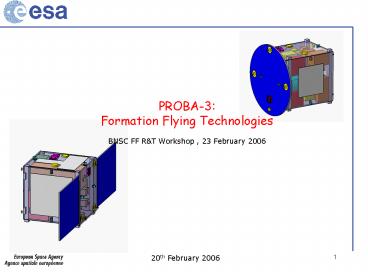
PROBA-3 Formation Flying Technologies
- BNSC FF RT Workshop , 23 February 2006
2
PROBA-3 Formation Flying Technologies
- Key Technologies for PROBA-3
- Mission Objectives
- Guidance Navigation Control
- S/W System Engineering
- RF Metrology
- Optical Metrology
- Propulsion
3
The PROBA-3 Mission Objectives
4
PROBA-3 Guidance Navigation Control Techniques
- Formation flying
- Deployment, Collision avoidance, FDIR
- Transition from decentralised to centralised
mode (science) - Maintain Formation along single axis (2
spacecraft) - 1 Imager 3 DOF (attitude)
- Occulter 6 DOF (attitude position)
- Coronograph
- - lateral positioning mm /- 2.5
- - longitudinal positioning mm /- 250
- - relative pointing error 1 arcsec over 1 sec
- - absolute pointing error 40 arcsec
- FF Demonstration / Optical Metrology
- - lateral positioning mm /- 32 (TBC) _at_ 250 m
separation distance - - longitudinal positioning mm /- 32 (TBC) _at_
250 m separation distance - FF Manoeuvres
5
PROBA-3 Guidance Navigation Control Techniques
- GNC Validation Strategy
- GNC Design Functional through simulation
- S/W validation through testbench
- Additional steps with H/W in the loop
- Ground Test Bed for validating RF optical
Metrology
6
PROBA-3 System SW Dev Lifecycle
Phase 2 Qualification AIT on EQM and Simulation
Phase I Design Validation by Simulation
Industry And Avionics System Lab
FF Lab SW Lab Matlab UML SDL
CDF SIMVIS
System Qualification
FF Mission/System
- System Qualification
- Testbench (EQM) -
Spec design
Industry
Functional Validation Testbench
ESA
GNC,MVM, FDIR
System integration
Spec design
-System HIL Testbench-
System prime
Software VV
Software
-Incremental releases Software
Validation Facility
Spec design (prototyping)
Software
Software test
Software supplier
Legend
Production
- unit/module level
- SDE -
Iterative system
development process
Transfer of facilities to contractor Test
procedures and Results
7
PROBA-3 Formation Flying Technologies
- System-software specification
- Modelling of system behavior (e.g. FDIR) with
model checking (SDL), and data modelling (XML,
ASN.1) - Modelling of the avionics architecture with a
case tool (UML, AADL) - Software design and production
- Real-time UML model of the SW architecture (
e.g. using HRT-UML or Artisan with HRT
stereotypes) including capsules for autocoded
components - Design and code generation with the qualified
tool SCADE (i/f with MatLab) - (Re-)Use of building blocks such as Operating
Systems, SOIF interface, core Data Handling
function, etc. - Verification and Validation
- Automatic test cases generation from UMLOCL
model with the Leirios tool - Verification support with Polyspace verifier
along the development process - Validation on SVF. EQM derived from SVF by
introducing hardware in the loop - ISVV of the mission critical functions
8
PROBA-3 Formation Flying Technologies
- LEON cross development environment
- C compiler, debugger, simulator
- Breadboards from Atmel and Pen board
- Hardware emulator (Astrium/Saab on-going, 2007)
- AeroJava for the higher Vehicle and FF Management
layers and software on-board maintenance - Goal safe re-programmability of on-board
software for flexibility - Maturity TRP/GSTP TRL 5/6 IN 2006Q3
- Operations based on File Management System
(GAMMA) and File Transfer Protocol - Maturity TRP TRL 4/5 lab demonstrator available
9
PROBA-3 Verification Facilities
PROBA Functional Engineering Simulator (Based
on Matlab)
PROBA Functional Validation Testbench (Based on
VSRF V.1)
PROBA Software Validation Facility (Based on
VSRF V.3)
PROBA EGSE Testbench (EQM) (Based on VSRF V.3)
PROBA 3 - Phase 1 (A/B)
2006
2007
2008
2009
2010
10
PROBA-3 RF Metrology
- The FF RF Subsystem provides
- the relative 3D position,
- velocity, attitude, attitude rate
- and local time between the FF SCs.
- Collision avoidance during deployment
- /nominal modes (quick navigation
- solution).
- Same design for all Rx/Tx units.
- Design valid for 2,3,4 S/Cs
- Each satellite transmits and receives
- (S-band, CDMA/TDMA). Two-way combination of
measurements for ranging. - Clock biases correction.
- Navigation processing centralised in nominal
configuration (coronagraph) - and decentralised during deployment.
- ISL capability (TM/TC) 4 kbit/s(FF), 12
kBit/s(Master)
11
PROBA-3 RF Metrology Design
The RF-Metrology per S/C will consist of 2 sets
of - 3 antennas (2Rx1Tx/Rx) - one RF TX/RX
unit
RF TX/RX unit
- mass 5.4 Kg
- size 290180130 (mm)
- power consumption
- 29 W (deployment),
- 20 W (nominal)
12
PROBA-3 RF Metrology - Performance
13
PROBA-3 Optical Metrology System
- Optical metrology system was initially developed
and breadboarded for the DARWIN constellation of
7 satellites (TRP activity 15645), but it is very
well applicable to the Proba-3 requirements. - Coarse lateral sensor
- Fine lateral sensor
- Longitudinal sensor
- Fringe tracking sensor
14
PROBA-3 Optical Metrology How does it work ?
Angular error ? 10"
Lateral error ? 1 full cone (? 4.4 m max)
Satellite 1
Angular error ? 10"
Satellite 2
Longitudinal error ? 10 mm
The starting configuration is obtained at the end
of the RF metrology acquisition phase
(Inter-satellite distance between 25 and 250
meters)
15
PROBA-3 Optical Metrology How does it work ?
Coarse Lateral Metrology Lateral error reduced
from /- 4.4 meters to /- 1 mm
Fine Lateral Metrology Lateral error reduced
from /- 1 mm to 10 µm/?Hz or /- 32µm _at_ 10 Hz
Absolute Longitudinal Metrology Longitudinal
error reduced from / -10 mm to /- 32 µm _at_ 10 Hz
Fringe tracking metrology Longitudinal error
remains 10 µm/?Hz or /- 32 µm _at_ 10 Hz, but is
stabilized to 2 nm/?Hz or /- 6.3 nm _at_ 10 Hz
16
PROBA-3 Optical Metrology
Makes additional use of RF metrology system to
obtain absolute distance, _at_250m ,
relative
THIS is not a minor subsystem !!!
17
PROBA-3 Propulsion
Large range of candidate propulsion technologies
today developed or under development -
Electric Propulsion FEEP, Mini-Ion. - Cold
Gas Selection depending on mission requirements

