4 Poly Etch Rate Variation - PowerPoint PPT Presentation
1 / 25
Title:
4 Poly Etch Rate Variation
Description:
Multi strip Poly resistors strips on the ends need Dummy strips. Closed-loop Dummies ... Layouts designs for serpentine resistors (fig.7.9) ... – PowerPoint PPT presentation
Number of Views:72
Avg rating:3.0/5.0
Title: 4 Poly Etch Rate Variation
1
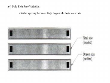
- (4) Poly Etch Rate Variation
- Wider spacing between Poly fingers ? faster etch
rate.
2
- Multi strip Poly resistors ? strips on the ends
need Dummy strips
3
- Closed-loop Dummies ? problem due
to inductive interaction with EM fileds. - Either break them up (fig.7.7) or at least have a
gap to stop current path.
- Dummies need electrical contact to the Tank.
4
- (5) Diffusion interactions
- Consider diffused-base resistors (fig.7.8)
- Diffused resistors usually are laid in a Tank
with NBL.
- Edges of diffused areas have diffusion tails. ?
resistors occupying the ends slightly
different values. ? use dummy resistors
(fig.7.8)
5
- Layouts designs for serpentine resistors
(fig.7.9) - Layouts in Tanks with deep-N sinkers (fig.7.9)
6
- (6) Stress Gradients and Package Shifts
- Packaging can exert stress onto Die.
- Metal Can package, Ceramic package, and Plastic
package
Metal Can package
7
Ceramic package, and Plastic package
8
- Metal Can package or Ceramic package ? lowest
stress - Use metal header plate, mounted using Epoxy.
- Solder or gold eutectic mounting ? higher stress
- Plastic package ? higher stress
- Epoxy resin for mounting
- Residual stress due to difference in CTE of Si
and Epoxy - Shifts in Offset voltage in OpAmp, Comparators,
or output ref. Voltage ? Package shifts
9
Coefficients of Thermal Expansion (CTE)
10
- Piezoresistivity
- N-type (100) Si
- Maximum piezoresistivity along lt100gt
- Minimum along lt110gt gtN-type diffused resistors
along lt110gt
11
- P-type (100) Si
- Maximum along lt110gt
- Minimum along lt100gt
- P-type diffused resistors along lt100gt
12
- (111) Si ? isotropic
13
- Gradients and Centroids
- Stress distribution on a Die surface isobaric
contour plot
14
- Place matched devices at Regions of lowest
stress gradients.
15
- Place matched devices at Regions of lowest
stress gradients.
16
- Matched devices must reside as close as possible
? minimize the stress
difference - Centroid of the device center of stress
distribution
17
- Common-Centroid Layout
- Example
- Two matched devices, A and B.
- Each device consists of two sections.
18
- Segmenting devices
- 1. Finding the greatest common factor
- Example 10kW and 25 kW ? 5kW segment size
- 2.Use the smaller device as basic segment
remainder should be gt 70 - Example 39.7kW and 144.3 kW ?
- Case-1 Use 39.7kW as a single segment. ?
144.3/39.7 3.637 (3 segments 25.2kW 64) - Case-2 Divide 39.7kW into two segments ?
unit 39.7 19.85kW ? 39,7kW 2 segments
144.3 144.3/7.27 7 segments
27 of unit. - Case-3 Divide 39.7kW into 3 segments ? unit
39.7/3 13.233kW ? 39.7kW 3 segments
144.3kW 144.3/13.233 10.904 10 segments
90 (11.97kW). - 3.Do not use too small a segment.
- 4.Make partial R segment using a sliding contact.
- 5.Capacitor segments should not have dimensions
much less than 100 mm2.
19
- Coincidence, Symmetry, Dispersion, and
Compactness
1-dimensional
20
- Coincidence, Symmetry, Dispersion, and
Compactness
2-Dimensional
- Cross-coupled pair
21
- Coincidence, Symmetry, Dispersion, and
Compactness
2-Dimensional
- Cross-coupled pair
- Tiling
22
- (7) Temperature and Thermoelectric Effect
- DIP or SOIC Tj Ta Pd qja
- Tj Junction temperature
- Ta ambient temperature
- Pd power dissipated in package
- qja junction-to-ambient thermal impedance
- 16-pin DIP qja 110 C/W
- 16-pin surface-mount (SOIC) qja 131 C/W
- Power package Tj Tc Pdqjc
- Tc case temperature
- qja junction-to-case thermal impedance.
- 3-lead plastic TO-220 Power Package qja 4.2
C/W - 3-lead metal TO-3 can power package qja 2.7
23
- Thermoelectric effect ET S DTc
- S Seeback coefficient ( 0.4mV/C)
- DTc temperature difference between two contacts
of the resistor - Example 0.4mV offset in Bipolar mirror produces
1.5 mismatch in the currents.
Power device
24
(No Transcript)
25
(No Transcript)

