Longwave Infrared LWIR Coded Aperture Dispersive Spectrometer - PowerPoint PPT Presentation
1 / 1
Title:
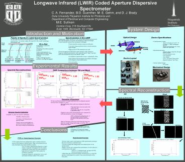
Longwave Infrared LWIR Coded Aperture Dispersive Spectrometer
Description:
Mask yields high spectral resolution and high throughput. Slit vs. Mask ... problem of high precision required for FTIR systems for resolution constraints. ... – PowerPoint PPT presentation
Number of Views:53
Avg rating:3.0/5.0
Title: Longwave Infrared LWIR Coded Aperture Dispersive Spectrometer
1
Longwave Infrared (LWIR) Coded Aperture
Dispersive Spectrometer
C. A. Fernandez, B.D. Guenther, M. E. Gehm, and
D. J. Brady Duke University Fitzpatrick Institute
for Photonics and Department of Electrical and
Computer Engineering
M.E. Sullivan Centice Corp, 215 Southport
Dr, Suite 1000, Morrisville, NC 27560
System Design
Introduction and Motivation
Optical Design
Device Specifications
Family of Aperture-coded Spectrometers
Spectrometers in the LWIR
We have been involved in the development of
various coded aperture spectrometers. Our systems
replace the input slit with a mask containing a
well-defined code.
- Traditionally, Fourier transform (FTIR) based
spectrometers are known for their high throughput
(Jacquinot) and multiplex (Felgett) advantages.
Fourier transform systems face mechanical
challenges. - Fourier-transform systems contain movable parts
- Can require long acquisitions times to record
maximum signal strength - High precision FTIR instruments are costly
- We have designed and fabricated a static
aperture-coded, dispersive longwave infrared
spectrometer with a spectral band of 9µm-11µm
that uses a microbolometer array at the detector
plane. - Our dispersive spectrometer is static
mechanically robust. - Mask exhibits both throughput and multiplex
advantages for the dispersive-based spectrometer. - Low cost system
- Coded aperture at input
- Based on Hadamard code N12
- 3.54mm x 1.08mm rectangular aperture
- Pattern electroformed onto 11mm nickel disc 50µm
thick - Microbolometer array
- Detects change in heat flux through internal
resistor - Uncooled detector array
- Low resolution
- Low fidelity
- 160 x 120 pixels (30µm pitch)
- Spectral response 7µm-14µm
- Custom Optical Design
- f/2 system
L2
L1
MIRROR
Focal Plane
Slit vs. Mask
MASK
- Throughput is limited by aperture size
- Widening slit sacrifices spectral resolution
- Mask (coded aperture) is a regular pattern of
many, small transmissive and opaque openings - Mask yields high spectral resolution and high
throughput
FOCAL PLANE
Dispersive Element
GRATING
L3
L4
Device Layout
Coded aperture High throughput, high resolution.
Narror Slit Poor throughput, high resolution
Wide Slit High throughput, poor resolution.
Experimental Results
Mechanical Design
Spectral Reconstructions
SNR Comparison between Slit and Mask
SNRMASK
SNRMASK
SNRMASK
1.69
3.49
1.82
SNRSLIT
SNRSLIT
SNRSLIT
Spectral Reconstruction
Slit
Mask
IMAGE AT DETECTOR
Description of Experiment
- We have performed a proof of concept experiment
by recording the spectral emission from a tunable
CO2 laser. - Reconstructions from a slit were compared to that
from the mask - The mask feature size was equal to the width of
the slit. - The height of the slit was comparable to that of
the mask. - Signal-to-noise (SNR) measurements were compared
for both slit and mask at various wavelengths. - SNR is obtained by taking the ratio of the
spectral peak and the standard deviation of the
spectral noise (noise floor) - Ratio of deviation of the pixel value from the
mean was taken for a single background image, as
well as, 100 background images. - For all pixels in a single background image the
deviation was about 14.49. - Averaging 100 background images yielded a
deviation between 0.01 and 0.06.
Emission Spectral Calibration
SHUFFLED HADAMARD N12
BINNING
Emission Spectral Calibration
- A tunable CO2 laser was used for calibration.
- Tunable, coherent source.
- Provides a well characterized spectral feature.
- Data at various wavelengths are saved for use in
the calibration of the x-axis in future
reconstructions.
BINNED DATA
NNLS ESTIMATES
BINNING
Conclusions
Experimental Overview
RECONSTRUCTION
FTIR vs. Coded Aperture Overview
- We have built a static coded aperture LWIR
spectrometer prototype that can reconstruct a
coherent source. - We have modeled the background noise
characteristics of our optical system. - Finally, we have also compared the performance of
a slit to that of a coded aperture at the input. - With a N12 Hadmard mask, an improved SNR factors
are measured over the slit. - While there have been shortcomings with this
device, it is the first aperture-coded dispersive
system to use a microbolometer at the focal plane.
- FTIR systems have been traditionally used to
examine emission spectra in the longwave infrared
region. High cost and precision are some
drawbacks associated with these systems. - Use of a static coded-aperture dispersive system
obtains comparable throughput from the sample. - Making the system static solves the problem of
high precision required for FTIR systems for
resolution constraints. - In general, dispersive systems have lower costs
associated with them unlike FTIR systems.


