Summary: - PowerPoint PPT Presentation
1 / 1
Title:
Summary:
Description:
There are a couple possible reasons for the discrepancy between the ... Aeronautical Engineering Department Civil and Environmental Engineering Department ... – PowerPoint PPT presentation
Number of Views:29
Avg rating:3.0/5.0
Title: Summary:
1
The Use of CFD and Wind Tunnel Studies to
Optimize Passive Sampler PerformanceR. Paul
Ashman1, Justin Thomas1, Thomas M. Holsen2 and
Suresh Dhaniyala1, Clarkson University, Potsdam,
NY 13699¹ Mechanical and Aeronautical
Engineering Department ² Civil and Environmental
Engineering Department
Development of a New Passive Sampler
Instrument Descriptions
Abstract A commonly used passive sampler (Jaward
et al., 2004) is evaluated using computational
fluid dynamics (CFD). Experimental studies with
these samplers have shown that they sample at
rates, which are largely independent of the
ambient wind conditions (Tuduri et al., 2005).
Additional experiments designed to verify the
velocities predicted by the computational fluid
dynamics research reveal a maximum discrepancy of
3 times between computational and experimental
results. Sampling rates calculated assuming the
PUFs are perfect sinks are greater than those
obtained experimentally at similar internal
velocities. The variable sampling rate slopes
found experimentally for PCBs can be attributed
to differences in boundary layer characteristics
over the PUF. CFD modeling of screens suggest
that the use of screens significantly reduces the
sampling rate seen in the samplers.
Hot Sphere As the wind velocity around the hot
sphere changes, it remains at a constant
temperature. The system measures the changes in
voltage required for this condition. Sonic
Anemometer Determines wind velocity by comparing
the travel time of two ultrasonic pulses. Pulse A
travels from transducer A to B and pulse B
travels in the reverse direction.
- Idea use of optimally placed multiple screens
that minimize convective wind velocity affects of
the species uptake rate in the sampler.
Flow Direction
Calibration Challenges Problem A change of 1 C
in ambient temperature causes velocity magnitude
errors of 15 at 0.1 m/s in the hot sphere.
Figure 8a and 8b Model Domain for Screen
Simulation
Figure 3 Harner Sampler (left) and Tisch Sampler
(above).
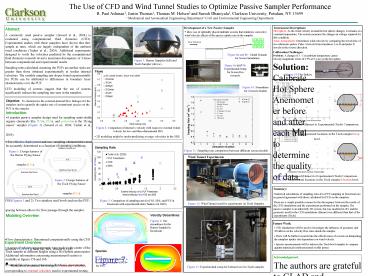
Solution Calibrate Hot Sphere Anemometer before
and after each trial to determine the quality of
data.
Figure 9a and 9b Experimental Setup for Screen
Box research.
Flows
Figure 14 Hot Sphere
Figure 10 Streamlines for 3-Screen Models
Objective To characterize the external-internal
flow linkages for the samplers and to quantify
the uptake rate of contaminant species on the PUF
in the sampler.
Introduction
- A popular passive sampler design used for
sampling semivolatile organic chemicals like
PCBs, PAHs, and pesticides is the flying saucer
sampler (Figure 3) (Jaward et al., 2004 Tuduri
et al., 2005). - For effective deployment and use, sampling
characteristics must be accurately determined as
a function of operating conditions.
Figure 15a Numerical (Harner) to Experimental
(Tisch) Comparison. Figure 15b Measurement
locations in the Tisch samplers top bowl.
Figure 4 Comparison of internal x-velocity with
respect to external (wind) velocity for two- and
three-dimensional SBS.
- 2D modeling might be under-predicting average
velocities in the SBS.
Sampling Rate
Figure 11 Sampling rate comparison between
different screen models.
Figure 1 Design features of the Harner Flying
Saucer sampler (FSS).
Wind Tunnel Experiments
Figure 16a Numerical (Harner) to Experimental
(Tisch) Comparison. Figure 16a Measurement
locations in the Tisch samplers bottom bowl.
Figure 2 Design features of the Tisch Flying
Saucer sampler (FSS).
Summary Numerical calculations of sampling rates
for a PUF sampling in freestream are in general
agreement with those calculated for PUFs in the
samplers. There are a couple possible reasons for
the discrepancy between the results of the CFD
simulations and the experiments performed on the
sampler. The passive sampler is an inherently 3D
system, but was modeled in 2D, and the geometry
used for the CFD simulations (Harner) was
different than that of the experiments (Tisch).
- FSS (Figures 1 and 2) Two stainless steel bowls
enclose the PUF spacing between allows for flow
passage through the sampler. - Flow characteristics Determined computationally
using the CFD software FLUENT (Fluent Inc, MA
Version 6.1.22). - Simulations conducted for a range of freestream
velocities, corresponding to external velocities
used in experimental testing.
Figure 5 Comparison of sampling rates for FSS,
SBS, and PUF in freestream with experimental data
(Tuduri et al 2005).
Figure 12 Wind Tunnel used for experiments on
Tisch Sampler.
Modeling Overview
Velocity Streamlines
Figures 6 The streamlines for the Harner Sampler
in freestream .
Future Work
- CFD simulations will be used to investigate the
influence of geometry and 3D affects on the
velocity flow rates inside the sampler. - There will be further research into the
effectiveness of screens on dampening the
samplers uptake rate dependence on wind velocity.
- Species measurements will be taken in the Tisch
bowl sampler to compare against numerical results
presented on this poster.
Experiment Overview
- A series of velocity measurements were made in
the center of the Tisch sampler at different
heights using a Hot Sphere anemometer. Additional
information concerning measurement location is
available in figures 15b and 16b. - External Velocities were measured with a Sonic
Anemometer.
Species
HMWC mass fraction contours in vicinity of
PUF for FSS.
Figure 7
Acknowledgement
The authors are grateful to GLAD and Environment
Canada for financial support of this project. We
would also like to thank Tom Harner for his
valuable insights and Ludovic Tuduri for making
experimental sampling rate data available.
Figure 13 Experimental setup for bottom bowl in
Tisch sampler.


