Membrane Structures for Communications Satellites - PowerPoint PPT Presentation
1 / 13
Title:
Membrane Structures for Communications Satellites
Description:
All Secondary Components Made From SRS CP1. Aluminum Coated Both ... Drying the Precipitate (Imide powder) Use the Highest. Grade Monomer. Perform Thermal ... – PowerPoint PPT presentation
Number of Views:33
Avg rating:3.0/5.0
Title: Membrane Structures for Communications Satellites
1
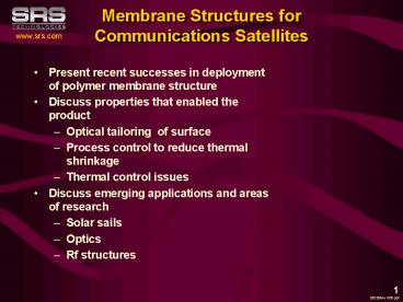
Membrane Structures for Communications Satellites
- Present recent successes in deployment of polymer
membrane structure - Discuss properties that enabled the product
- Optical tailoring of surface
- Process control to reduce thermal shrinkage
- Thermal control issues
- Discuss emerging applications and areas of
research - Solar sails
- Optics
- Rf structures
001206Ae1535.ppt
2
Hughes HS702 Summary
SRS and HSC Co-developed the Reflector Panels for
the 702.
- SRS Is the Exclusive Provider of Reflector Panels
for the 702 Program. - Currently have Orders for Over 11 Satellites.
- Four are on-orbit.
- G11, Anik F, Pas 1R, Thuraya
- Represents 2B in satellite assets being powered
in Geo currently - 160 2 meters of film per satellite
- Film is 1 mil material supported by 5 mil edge
designs.
- Surface Designed for Tuned Optical Properties
- CP1 Panels Are Extremely Flat With Isotropic
Material Properties - All Secondary Components Made From SRS CP1
- Aluminum Coated Both Sides
Patented Technology
001206Ae1526.ppt
3
General Philosophy of Approach
- Utilize processes which allow film structures to
be fabricated from materials which can be
tailored for specific applications - Allows user to reduce anisotropic properties
- Control properties to some extent
- Vary thickness of material
- Control product from monomer state
- Construct films in a variety of shapes
- Flat
- Parabolic
- Segmented compound curvatures
001206Ae1527.ppt
4
Materials Used
Initial Materials Monomers -- 6-FDA 1,3-3APB 4-B
DAF
- SRS Exclusive licensed CP1/2 material from NASA
LaRC - UV, e-rad resistant
- Flight qualified at BSS for 15 year GEO life
- For high performance applications consider
specialty film not manufactured in large
quantities.
Use the Highest Grade Monomer
Polyamic Acid Prep 6-FDA 4-BDAF (CP1)
Polyamic Acid Prep 6-FDA, 1,3-3APB (CP2)
Viscosity Rise Indicates Quality
Chemical Imidization Procedure (stabilizes
reaction)
Precipitation Procedure (to make solid)
Perform Thermal Analysis to Assure High Quality
Drying the Precipitate (Imide powder)
001206Ae1440-ppt
5
Optical Properties (Key)
- Tuned diffusivity based on Flight specifications
- Increased flatness due to the material and
processes used to product CP1 film - Isotropic material properties
- Results in evenly distributed solar source on PV
array
Presented by C. Gelderloos, 28th IEEE PVSC
001206Ae1418.ppt
6
Thuraya Launch
- Five Panel Array Deployment
7
G11 Deployment at GEO
- First satellite launch and deployment of membrane
concentrator.
Hughes Award and NASAs Commercial Invention of
the Year
8
Membrane Structures Applications and Requirements
5 meter RF antenna
4 meter non-imaging solar collector
flat film mirror
Solar Collector
Membrane Optics
RF Antenna
RMS Wavefront Error
1-5x10⁻³ meter
lt1x10-3 meter
150x10-9 meter
RMS Slope Error
NA
2x10⁻³ Radian
1x10⁻⁶ Radian
RMS Thickness Variation
10
10
75x10-9 Meter
Conductivity
High
Charging
Charging
Optical Reflecting
NA
High
High
Increasing Difficulty
10
1000
1
001206Ae1528.ppt
9
Large Aperture Optics
- Working with AFRL Directed Energy Directorate to
make an optical imaging membrane. - Processing and monomer purity are the enablers
for membrane optics.
10
SRS Technologies CP1 Film
11
Carbon Nanotubes as Process Modifiers
- Carbon Nanotubes were added to SRS CP1 film to
alter the material properties of the films. - Three different mixture ratios were used 0.5,
2.5, and 5.0. - CTE decreased as Carbon increased as shown in
the graph below - Surface roughness increased with of Carbon.
- Opacity increased with Carbon 0.5 Light
Grey, 5.0 Black - There appears to be a slight increase in strength
with a maximum occurring between 0.5 and 5.0.
001206Ae1602.ppt
12
Metallizing Reaction Mechanism
- Desire to go to higher frequency applications
- Polymeric material becomes a player in the
insertion loss. - Thermal Control of composite structures are an
issue.
001206Ae1111.ppt
13
Conclusions
- Newly developed polymers and processes are being
used to enhance the performance of space
satellites. - We are active in RD which will reach the
warfighter. - The Chasm has been crossed.
001206Ae1110.ppt
14
Solar Sails
- x
15
Use Government Labs
- Work in large facilities that have
state-of-the-art equipment
NASA MSFC Dynamics Vacuum Chamber
NASA GRC 2x3 m Off-Axis Concetrator in Tank 6
NASA MSFC Large Mandrel Machining
16
Other Projects

