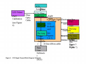
Figure 1: ICD Single Channel Block Diagram Schematic - PowerPoint PPT Presentation
1 / 13
Title:
Figure 1: ICD Single Channel Block Diagram Schematic
Description:
(Located In LV Fanout Box) 50 O SMA 316 Belden Coaxial Cables (X128) ... ECL Pulse (digital) To La Tech ICD Motherboard. 50 s. The first 400 ns of this pulse ... – PowerPoint PPT presentation
Number of Views:78
Avg rating:3.0/5.0
Title: Figure 1: ICD Single Channel Block Diagram Schematic
1
Figure 1 ICD Single Channel Block Diagram
Schematic
2
Figure 2 La Tech ICD Motherboard
3
Figure 2a Picture of the production ICD
Motherboard with inputs and outputs marked
4
16 Light Tight Boxes containing Motherboards
Figure 3 Layout of ICD Crate Electronics and
Motherboard
5
MOD Maryland Box (X8)
1-to-3 HV Fanout Board (shown in Figure 4a)
SHV Cables 16 channels
Run I HV POD (X16)
8 Outputs _at_1000-800 VDC
Individual FUSES on HV output tp PMTs (see
Figure 4a)
Variable Resistors on output
48 channel output on Six 8-conductor Reynolds
cables
Old Maryland Box (X24) 1-to-1 Fanout
SHV Cable
To ICD Motherboard
Figure 4 High Voltage Supply Block Diagram
6
Fuse
Fuse
Fuse
Figure 4a Circuit Diagram for the High Voltage
Fanout Board
7
Figure 5 Low Voltage Power Supply Block Diagram
8
Figure 5a Circuit Diagram for the Low Voltage
Fanout Board
9
Figure 6 PMT LED Calibration Pulser Diagram
10
Figure 7 PreAmp Calibration Pulser Diagram
11
Figure 8 Plat Form Layout of ICD Racks
12
D0 North End
Face of Endcap Calorimeter
ICD Box (Contains 12 Tiles)
ICD Scintillator Tiles
Notes 1. There are 16 ICD Boxes for each End
with 12 Scintillator Tiles in each (gives
12x16192 signal channels per end) 2. Connection
from Tiles to ICD Crates is through a 5m
long Fiber Cable 3. There are 2 ICD Electronics
Crates each contains 16 ICD Electronics
Boxes 4. Each ICD Electronics Box handles 6
PMTs (2 ICD Electronics boxes per Tile)
Fiber Cables
Upper Cable Tray
ICD Crate
Iron Boxes ( surrounds PMTs)
View Looking South
LV Fanout Boxes
Lower Cable Tray
Figure 9 Inner Cryostat Detector System - ICD
13
Figure 10 Expanded view of ICD Layout with
dimensions.


