Main Rotor Head - PowerPoint PPT Presentation
1 / 18
Title:
Main Rotor Head
Description:
Main Transmission Oil Level. Dipstick (ensure secure after checking has ... This gauge only present if winterization kit installed. Cabin Interior AN/AQS-22 ... – PowerPoint PPT presentation
Number of Views:289
Avg rating:3.0/5.0
Title: Main Rotor Head
1
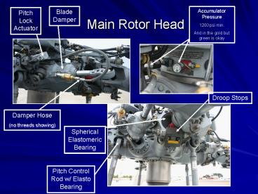
Main Rotor Head
Blade Damper
Accumulator Pressure 1200 psi min. And in the
gold but green is okay
Pitch Lock Actuator
Droop Stops
Damper Hose (no threads showing)
Spherical Elastomeric Bearing
Pitch Control Rod w/ Elasto Bearing
2
Main Rotor Head cont.
De-Ice Spider Harness
Anti-flap Cam
Blade Lockpin Puller
Scissors Bearing
BIM Indicator
3
Fwd XMSN/Rotor
Main Mast
Scissor Assembly
PCR
Rotating Swashplate
Stationary Swashplate
4
Main Rotor Brake Disk
Gust Lock (Tiny Silver Gear)
Main Transmission Oil Level Dipstick (ensure
secure after checking has both hot and cold
levels)
Utility Hydraulic Pump
5
Engine Compartment
IPS Exhaust Blown out through the gap between the
engine exhaust and engine exhaust cowling
Accessory Gearbox
TGT Harness
IPS Blower
Fuel Filter
Engine Oil Filter w/ PDI
HMU
Pneumatic Starter
LDS
PAS
Deswirl Duct Clamp
Oil Filler Cap
6
Engine cont.
Viewed from port
Check pins (1 of 2, the other is out of view
behind bleed air line)
HMU Variable Geometry (VG) servo
7
Transmission Oil Cooler Compartment
Reservoir Indicating System
1 Driveshaft
Utility Hydraulic Reservoir 2 PDIs
Rotor Brake Accumulator (White Tube)
XMSN Oil Cooler Fan
Thomas Coupling Less than a dime with of
separation
Crossbleed Air Lines
8
APU/ECS Compartment
Combustor
Upper SATCOM Antenna Cable
Heat Exchanger
ACM
APU Oil Filler Cap/Dipstick
J-Tube
Starter
Water Separator
High Press Sensor
FWD
IRCMPlugs
APU
ECS
Bleed Air
9
Fire Bottle Compartment
1/2 Fire Extinguisher Bottles (pressure table
on side of each)
Tail Driveshaft Connect w/ Thomas Coupling
10
Tail Landing Gear
Tail wheel Manual Lock Lever Up for flight down
for ground
Slip Mark
Shimmy Damper
11
Tail Pylon Hinge Intermediate Gearbox
Tail Rotor Servo Hydraulic Line Hinge Fittings
(check for leaking 1 drop per day allowed)
IGB Oil Filler Cap
Pylon Fold Hinge/ Lockpins
IGB Oil Bullseye
Tail Pylon Step
12
Tail Driveshaft Disconnect Spring
Disconnect Jaws
Thomas Coupling
Viscous Damper
13
Stab Lockpins
Lower Stab Actuator
The four bolts around the STAB do not face the
same direction 1 face aft and 3 face forward
Tail Bumper
14
Anti-collision Light (Note screw installed in
top of upper light, not installed on lower
light, to allow water to drain)
Tail Rotor
Spring Cylinders
Blade Boot
Tail Rotor Quadrant
Flexible Thomas Coupling
Tail Rotor Servo
Number 6 Driveshaft
Centering Springs
Hydraulic Lines
Cable and Pulley (each side of Quadrant)
15
Bonding Wire
Indexer (retracted)
Pitch Change Links
Pitch Beam Retainer Nut
Pitch Change Beam
Tail Gearbox Oil Level
16
Cabin Interior
Crew Hover Control
Accumulator Pressure Min 2,650psi
HIFR Pressure/APU
Aft Bulkhead Gauges
Rescue Hoist Pendant
This gauge only present if winterization kit
installed
Backup Rescue Hoist Power
Rescue Station
HIFR Connection
17
Cabin Interior AN/AQS-22
Hydraulic Lines
Check security of all cannon plugs and hydraulic
lines
RMIU
Current First Aid Kit
Funnel Housing
No freeplay allowed
REMOTE/Parking Selector
RAST
18
RAST Probe
Cargo Hook As pictured here, a Breeze Eastern
Model If the hook is totally enclosed it is a
Lucas Western

