NSTX TF Joint Failure - PowerPoint PPT Presentation
1 / 16
Title:
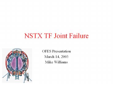
NSTX TF Joint Failure
Description:
NSTX TF Joint Failure – PowerPoint PPT presentation
Number of Views:17
Avg rating:3.0/5.0
Title: NSTX TF Joint Failure
1
NSTX TF Joint Failure
- OFES Presentation
- March 14, 2003
- Mike Williams
2
NSTX TF Joint Failure
- What happened?
- Why did the joint fail?
- What is our plan?
3
February 14, 2003 Following our morning test
shots, the first plasma attempt of the day
resulted in a loud bang (heard on the control
room audio monitors) accompanied by a plume of
smoke (visible on the control room video
monitors).
Power Supply Current Waveforms
4
Several protective devices tripped TF power
supply fault detector section overcurrent, TF
Analog Coil Protection (ACP) overcurrent, TF
Rochester Instrument System (RIS) overcurrent,
TF ground fault current relay. The target level
for the TF during this shot was 53.4kA which
produces Bt4.5kG. The fault occurred just prior
to reaching flat top as the current passed the
50kA level.
5
Initial inspection revealed that one of the TF
flags had been displaced by about 1 inch.
TF Flags
6
The TF flags are used to connect the outer leg
turns (red) to the inner leg turns (copper
bundle).
Hub Assembly
Umbrella Structure
TF Flags
7
TF flag schematic
EM Load
Hub Assembly
TF Bundle
TF Flag
Preload (bolts)
Hub Assembly
Shim
Keenserttm
8
Subsequent inspection (including removal of the
TF bundle) revealed the extent of the damage.
9
What happened?
- An open circuit fault (the flag joint opening up)
led to turn-to-turn (inner and outer legs) and
turn-to-ground faults (to the hub and umbrella
assemblies) at or near the high-voltage terminals
of the TF circuit. - This fault condition led to a spike of fault
current from the power supply which shunted the
coil inner/outer leg assembly. - Once the power supply tripped, the current spike
decayed. - This was followed by an L/R decay of the coil
current as the coil released its stored energy.
(Although the L/R decay was not typical, it has
been modeled by an arc across the open flag
joint.) - The energy dissipated in the arc was of order
1.4MJ.
10
Why did the joint fail?
- Subsequent analysis has revealed that the present
design was unable to maintain the required joint
pressure - Bolts alone could not adequately withstand the
additional electromagnetic load in addition to
the initial preload, - Shims did not adequately transfer load to the hub
assembly.
11
Prior to this run period, we were concerned about
these joints.
- During the past outage (after two weeks of 6 kG
operation) we identified systemic issues of
loosened bolts, mushrooming copper around bolt
holes and increased joint resistance. - We delayed completing the outage to address these
concerns - Resurfaced flag faces, which were not perfectly
aligned, and chamfered bolt holes (bottom), - Improved bolt washers and bolt retention (top and
bottom), - Retorqued bolts (top and bottom) and replaced 4
keensertstm with tap-loktm inserts
(bottom), - Replaced G-10 flag shims with inflatable epoxy
shim design (top and bottom). - We derated the TF and instituted an accelerated
inspection program during maintenance weeks for
the FY03 campaign.
12
After 3 run-weeks in FY03, we inspected the
joints.
- Plan was to inspect 4-6 joints on the top of the
machine plus the leaking coolant path (6A), - Found several loose bolts so we inspected (and
retorqued when necessary) all of the upper
joints, - Found one joint resistance out of spec and broke
one Keenserttm while tightening bolt, - The new epoxy shims were tight,
- The 6A coolant path was still leaking (as well as
a smaller internal leak in 8A), - We planned to continue inspections during
maintenance weeks while limiting operation to 4.5
kG. - Design of a new TF bundle/flag joint was underway.
13
We have now accelerated the redesign effort.
- We understand the weaknesses in the present
design - We have analyzed the fault data and inspected the
damaged components, - We have refined our models of the joint design
and performed more analyses.
14
There are significant design issues
- Maintaining contact on the joint face
- Bolt design needs to accommodate preload as well
as electromagnetic and thermal loads, - Design needs to accommodate shear on the joint
face while minimizing electrical resistance. - Transferring the mechanical loads (via the hub
assembly) to the torque collar - Shims were a weakness in current design.
- Determine whether the current hub assembly/torque
collar is adequate for the additional loads. - More robust cooling channel
- New design will incorporate rigid, thicker-walled
piping - Eliminate external bends.
15
We plan to complete our design activity in the
next few weeks.
- Presently testing prototype joint design
concepts, - Complete joint/bundle design by early-April,
- Final Design Review (inviting participants from
C-MOD, MAST, DIII-D, UW and FFOC) on April 10, - FDR will incorporate findings from Laboratory
review committee.
16
We are developing a plan which should have us
back in operation this Fall.
- Vacuum vessel pumpdown mid-June followed by
bakeout, - Complete machine clean-up and preassembly testing
by July, - Complete manufacture of new TF bundle by August
- The bulk of the machining will be done by an
outside vendor, - We plan to assemble the new TF bundle in-house,
- Complete machine reassembly by October,
- Begin power testing October 20,
- Begin plasma operations November 3.


