Outline - PowerPoint PPT Presentation
1 / 11
Title: Outline
1
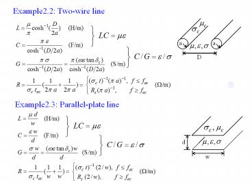
Example2.2 Two-wire line
?
Example2.3 Parallel-plate line
2
Wave Equations of Transmission Line
Time-harmonic T.L. (Telegrapher) equations
General solutions (traveling-wave solutions) of
transmission-line equations yield
V(z)
I(z)
where
- Characteristic Impedance, Unit?
ps. The parameters ? and Z0 are called
transmission line parameters.
3
- Lossless Transmission Lines
(Lossless conditions R G0)
- Low-Loss Transmission Lines
(Low-loss conditions Rltltw L, Gltlt w C)
Therefore,
where ac is attenuation due to conductor loss
ad is attenuation due to dielectric loss
4
Example2.4
- For low-loss coaxial lines,
- For low-loss two-wire lines,
- For low-loss parallel-plate lines,
5
- Distortionless Lines
- Lossy line has a linear phase factor as a
function of frequency.
- Relation
- Verification
- Advantage Distortionless line transmitted
signal without dispersion.
Dispersion If the phase velocity is different
for different frequencies, then the individual
frequency components will not maintain their
original phase relationships as they propagate
down the TL, and signal distortion will occur.
6
- Why 50? characteristic impedance for coaxial
lines?
- From distributed parameters
- From transmission-line parameters (Considering
minimum loss)
Attenuation constant due to conductor loss
Attenuation constant due to dielectric loss
Assuming that the outer dimension b is fixed, ?c
has a minimum when b/a3.591. The value comes from
7
- Considering the maximum breakdown voltage Vb
Then the maximum power capacity Pmax
Assuming that the outer dimension b is fixed,
Pmax has a maximum when b/a1.649. The value
comes from
Therefore, use 50? to compromise between 77? and
30?. (Also reference textbook p.130 point of
interest and problem 2.28 and 3.28.)
8
Z0
?c
Z0
Pmax
9
The Terminated Lossless TL
Zin
- Match conditions
Match Mismatch (Total Reflection)
Reflection coefficient 0 1
Return loss (RL,dB) ? 0
Standing wave ratio 1 ?
- Transmission line impedance equation
- Insertion Loss (IL)
10
- Terminated in short circuit
- Terminated in open circuit
11
Quarter-Wave Transformer
- A useful and practical circuit for impedance
matching. - Defined as TL with length equals to l?/4(
n?/2), n0,1,2,... - Perfect matching occurs at one frequency (odd
multiple) but mismatch will occur at other
frequencies. - Impedance matching is limited to real load
impedances (complex load impedance can be
transferred to real one, by transformation
through an appropriate length of line.)
Substituting ?l(2?/?)(?/4) ?/2 into equation
Zin can find
In order for ?0, one must have Zin Z0 , then
- Discussions


![[PDF] DOWNLOAD FREE Clinical Outline of Oral Pathology: Diagnosis and PowerPoint PPT Presentation](https://s3.amazonaws.com/images.powershow.com/10076578.th0.jpg?_=20240711025)

![[READ]⚡PDF✔ Black Letter Outline on Contracts (Black Letter Outlines) 5th Edition PowerPoint PPT Presentation](https://s3.amazonaws.com/images.powershow.com/10044064.th0.jpg?_=20240531080)


