Engineering Inc' Me 358 Mechanism Analysis - PowerPoint PPT Presentation
1 / 17
Title:
Engineering Inc' Me 358 Mechanism Analysis
Description:
Analytical analysis was completed in MathCAD, and Excel was used to compare the ... MathCAD. AutoCAD. Working Model. Excel. Other Resources. Design of Machinery ... – PowerPoint PPT presentation
Number of Views:64
Avg rating:3.0/5.0
Title: Engineering Inc' Me 358 Mechanism Analysis
1
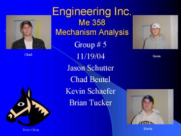
Engineering Inc.Me 358 Mechanism Analysis
Chad
Jason
- Group 5
- 11/19/04
- Jason Schutter
- Chad Beutel
- Kevin Schaefer
- Brian Tucker
Kevin
Bronco Brian
2
Abstract
- The assigned project asked for a system of
four-bar linkages arranged to produce a
straight-line output of nine inches. The
mechanism was to fit in the smallest possible
area given the design guide lines 9 inch
vertical output, 10 inches/sec max velocity,
motor located 3 feet from output in a 1 foot by 2
foot box, and a 6 inch clearance of all linkages
with shop floor. The product design task was
resolved using a four-bar linkage in conjunction
with a Tchebicheff four-bar linkage. After the
mechanism was finalized, it met the required
specifications and fit into an area 5 feet long
by 3.5 feet high with 6 inches of clearance.
3
Introduction
- Graphical and analytical analysis was performed
for position, velocity and acceleration on the
system at the point where vertical motion has the
greatest velocity (VP 9.991 in/s). Working
Model was used to draw a scale model of the
system and to confirm that it met all
requirements. Analytical analysis was completed
in MathCAD, and Excel was used to compare the
results of our graphical and analytical analysis.
4
Working Model
5
Graphical Mechanism
All measurements in inches
6
Graphical AnalysisMechanism 1
- Position Analysis
- q3 270
- q4 206
- Velocity Analysis
- VA 2.4348 in/s _at_ 90
- W3 0.2378 rad/s CW
- VB 2.7 in/s _at_ 305
- W4 0.238 rad/s CW
- Acceleration Analysis
- AA 4.9402 in/s2 _at_ 180
- AB 0.646 in/s2 _at_ 26
- a3 1.0874 rad/s2
- a4 0 rad/s2
7
Graphical AnalysisMechanism 2
- Position Analysis
- q3 0
- q4 63
- Velocity Analysis
- VA-11.1456 in/s _at_ 334
- W30.9287 rad/s CCW
- VB-11.1456 in/s _at_ 26
- W40.238 rad/s CCW
- VP10 in/s _at_ 0
- Acceleration Analysis
- AA7.392 in/s2
- AB2.6526 in/s2
- a30.157 rad/s2
- a40 rad/s2
8
Analytical AnalysisMechanism 1
9
Analytical AnalysisMechanism 1
10
Analytical AnalysisMechanism 1
11
Analytical AnalysisMechanism 2
12
Analytical AnalysisMechanism 2
13
Analytical AnalysisMechanism 2
14
Analytical AnalysisMechanism 2
15
Results
16
Conclusion
- In conclusion, the combination of the two
four-bar mechanisms resulted in a 9 vertical
motion of a point on link B of mechanism 2. To
achieve an output velocity of 10 in/s the motor
attached to link A on mechanism 1 must have an
angular velocity of 2.029 radians per second or
19.38 revolutions per minute. The work space was
minimized to a 5 foot by 3.5 foot area with 1
wide links.
17
Resources
- Computer Programs
- MathCAD
- AutoCAD
- Working Model
- Excel
- Other Resources
- Design of Machinery R.L. Norton
- www.brockeng.com


