Alignment constants of the FPix in CMS Detector.
1 / 9
Title:
Alignment constants of the FPix in CMS Detector.
Description:
... both sides with detectors (paper) and fiducial marks (pattern to be ... 2. Survey with touch probe the fiducial balls on both sides of the -Disk and then both ... –
Number of Views:43
Avg rating:3.0/5.0
Title: Alignment constants of the FPix in CMS Detector.
1
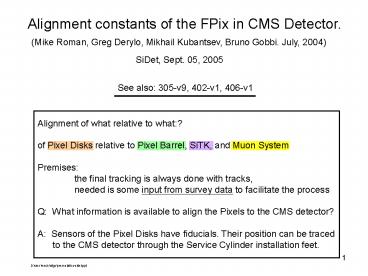
Alignment constants of the FPix in CMS Detector.
(Mike Roman, Greg Derylo, Mikhail Kubantsev,
Bruno Gobbi. July, 2004)
SiDet, Sept. 05, 2005
See also 305-v9, 402-v1, 406-v1
Alignment of what relative to what? of
Pixel Disks relative to Pixel Barrel, SiTK, and
Muon System Premises the final
tracking is always done with tracks, needed is
some input from survey data to facilitate the
process Q What information is available to
align the Pixels to the CMS detector? A
Sensors of the Pixel Disks have fiducials. Their
position can be traced to the CMS detector
through the Service Cylinder installation feet.
D\cms\mech\align\presentation-sidet.ppt
2
One must trace the position of the
Pixel Sensors ½-Disks
½-Service
Cylinder
CMS Detector
Survey
Survey
200 µm Mech.
Have fiducials
Survey
Have alignment balls
Installation Pins
D\cms\mech\align\presentation-sidet.ppt
3
Fiducials on FPix Sensors
Fiducials
1 x 1 sensors
60 µm full size
Kim Jiolo, June 03. This picture is obsolete.
See Doc. 406-v1
D\cms\mech\align\presentation-sidet.ppt
4
Alignment Balls on ½-Disks
Accessibility of Balls with Objective tested at
SiDet with old and new Adapter Board.
Dcms\mech\align\ball_1_3_4-c.ppt
5
Obstructions (?) to the survey caused by the
new Adapter Board
Adapter Board
D\cms\mech\align\presentation-sidet.ppt
6
Limited access to the survey fiducials on the
Plaquettes (overlap of Panels). Also limitations
caused by the Adapter Board. See Greg Derylo.
D\cms\mexh\alignm\12-may_1-c.ppt
7
Proposed Survey Plan
½-Disk assembled and not installed in ½-Serv.
Cylinder
- 0 The ½-Disk is located flat on the surveying
equipment. - The coord. System of the ½-Disk is determined by
two reference holes - machined in the Outer Ring. Survey with
touch probe. - Measure optically on one side (3 Panels or 4
Panels) of the assembled - ½-Disk, the position of a few (visible)
sensors fiducials on each - Plaquette of the 12 Panels.
- Also measure optically the position of the
Alignment Balls on the same - side of the ½-Disk (on Inner and Outer
Ring). - Measure with a touch probe the alignment of the
Alignment Balls (on - Inner and Outer Ring) of the same side of
the ½-Disk. The use of objective - or touch probe are interchangeable without
distorting the measurements. - Repeat the same measurements on the other side of
the same ½-Disk.
8
Proposed Survey Plan, cont.
After all the ½-Disk have been installed in the
four ½-Serv. Cylinders, (electrically) tested,
and perform as designed, each ½-Disk will be
surveyed relative to the Installation Pins of the
½-Serv. Cyl.
We believe that the position of the Alignment
Balls, on the ½-Disk, can be Surveyed with the
touch probe after the Disk have been installed in
the ½-Serv. Cyl. and tested. (This has not been
tried with the model.)
- For each ½-Disk installed in the ½-Serv. Cyl.
Measure with the touch probe, - the position of the Alignment Balls (on
inner and outer rings) on both - sides of the ½-Disk. Also relate each set
of measurements to the 4 pins - used to install the ½-Serv. Cyl.in the CMS
detector. (Slide 2) - It is estimated that the ½-Serv. Cyl.
position relative to the CMS detector - will be known to about 200 µm. (This number
depends from the length of - the ½-Serv. Cyl. And the installation
rails.)
9
Proposed Test of Survey ½-Disk CMS-Pixel
June 30, 2004 (Mike Roman,
Greg Derylo, Michael Kubantsev, Bruno Gobbi)
- Coordinate system of the1/2-Disk is determined by
a hole machined in the outer ring on the x axis. - Survey sequence
- Survey position alignment balls on ½-Disk without
Panels. Survey both sides together. - Use touch probe.
- 2. Install Panels on both sides with
detectors (paper) and fiducial marks (pattern to
be - decided).
- 1. Survey optically 4 fiducials on each
Plaquette (Fiducials specified as 4 corners of a - rectangle) in coordinate
system reconstructed from alignment balls. - 2. Survey with touch probe the fiducial balls
on both sides of the ½-Disk and then both - sides at same time. This
step takes place in the carbon fiber of the
half-cylinder. - Cables/plumbing mockups
needed to test accessibility to survey balls on
downstream - of the half-disk.
- It is expected from this test
- Choose survey equipment (optical, touch probe)
- Ensure a collision free survey path.
- Decide optimal sequence of measurements.
- First experience with file of data.
D\cms\mech\mod\meas\surv-mod-fpix.ppt


