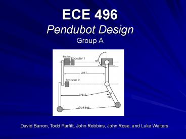
ECE 496 Pendubot Design Group A
1 / 30
Title: ECE 496 Pendubot Design Group A
1
ECE 496Pendubot DesignGroup A
David Barron, Todd Parfitt, John Robbins, John
Rose, and Luke Walters
2
The Creature
- Mechatronic System
- 2 Links, DC Motor, PC, Encoders, Interface Board
- Inverted Pendulum
- Control Feedback Loop
- Angular Position
- Output Torque
3
Overview
- Specifications and System
- John Rose
- Mechanical Design / Fabrication
- David Barron
- Mathematical Model
- John Robbins
- Software
- Luke Walters
- Conclusion
- Todd Parfitt
4
Specifications
- DC Motor
- Linear Amp Provided
- Mechanical Links
- 18 in. in Length
- Golf Ball Mounted On Link 2
- Sensors
- Measure Position
- No Manufactured Pos. Control Devices
5
System
- Mechanical Links
- Link 1
- Link 2
- Encoders
- Rotary Optical Encoders (Gurley Precision)
- DC Motor
- Dayton -1hp, 24V
- Linear Amp
- Server to Go
- Interface Hardware
- QMotor
- Control Program
6
Grainger Motor
- Motor Type Permanent Magnet DC
- HP 1
- RPM 1800
- Voltage (DC) 24
- Full Load Amps 39.0
- Rotation CW/CCW
7
Amplifier Power Output
8
ENCODERSGurley PrecisionInstruments
- Motion Type Rotary
- Usage Grade Light Industrial
- Output Incremental
- Max Resolution 1,800 counts/rev.
9
Aluminum Links
Link 2
Link 1
- 1 x 5/8 in Aluminum Bar Stoke
- Milled Slots
10
Properties of the Links
- Link 1 with Encoder
- Dimensions (mm) X 495.300
Y 25.4000 Z
15.8000 - Centroid (mm)
- X 278.666 Y 12.7000
Z 10.4693 - Mass (kg)
- 0.3944
- Link 2 with Ball
- Dimensions X 469.900
Y 25.4000 Z 15.8000 - Centroid X 331.628
Y 12.7000 Z 7.90000 - Mass (kg)
- 0.3374
11
Mathematical Overview
- The math provided for this system is as follows
- This equation is in the Euler-Lagrange format.
12
Math continued
- After some manipulation the form is changed to a
state oriented equation - The output of this system may be defined as
- y Cx Du
13
Math continued
- Another perspective
- Dynamics equations for a two link / two motor
system.
14
How do we find the solution?
- The solution can be found via matrix
manipulation. The equations required are
outlined in the 409 control text. - Mat Lab has a command called Linear Quadratic
Regulator that can automate the solution process.
15
The abbreviated version
- If we let
- And we define
16
The abbreviated version
- Such that
- The solution is found via the Algebraic Racacati
Equation
17
Ultimately
This K represents the gain values for the
controller.
18
SOFTWARE DEVELOPMENT
- Swing Up
- Open Loop
- Prototype 1
- Based on mathematical model
- Prototype 2
- Altered code to assist catch characteristics
- Prototype 3
- Case based sign adjustment
19
Swing Up
- Control
- Output swing back torque to motor
- Hold torque until swing back time limit
- Apply forward swing up torque
- Zero out torque when angle limit reached
20
Prototype 1
Control Loop Output 5V on Channel 1 to power
encoders Read Link1 and Link2 encoders
Convert encoder values to radians Calculate
angular velocity of Link1 and Link2 Filter
velocities to eliminate high freq noise
continued
21
Multiply Link 12 positions and velocities by
separate gains Sum the
products and multiply by tunable scalar Output
the calculated value to amplifier i.e. Vout
scalar ( k1q1 k2q2 k3V1 k4V2)
22
Observations of Prototype 1
- Pendubot would not catch and return to zero
- After using Matlab k-values and exhaustive
tweaking, no success
23
Prototype 2
Control Loop Output 5V on Channel 1 to power
encoders Read Link1 and Link2 encoders
Convert encoder values to radians Calculate
angular velocity of Link1 and Link2 Filter
velocities to eliminate high frequency noise
Sum Link 1 and Link 2 Positions MPY Link 12
positions, velocities, sum by gains Sum the
products and multiply by tunable scalar Output
the calculated value to amplifier i.e.
Vout scalar ( k1q1 k2q2 k3V1 k4V2
k5angSum)
24
Reasoning
Observe
T1 gt 0 T2 lt 0 T2 gt T1 Therefore T2 T1 lt
0 Torque is negative Vout .k5Sum)
L2
T2
T1
L1
Torque
MOTOR
25
Reasoning
Observe
T1 gt 0 T2 gt 0 Therefore T2 T1 gt 0 Torque is
positive Vout k5Sum)
T2
T1
L2
L1
Torque
MOTOR
26
Observations of Prototype 2
- Somewhat smoother control
- Helped to catch but not return to home
- Conflicted with mathematical model
T2
L2
T1
L1
T1 T2 0
27
Prototype 3
Control Loop Output 5V on Channel 1 to power
encoders Read Link1 and Link2 encoders
Convert encoder values to radians Calculate
angular velocity of Link1 and Link2 Filter
velocities to eliminate high frequency noise
Sum Link 1 and Link 2 Positions If (sign of sum
is opposite that of Link1 Position) then flip
sign of Link1 Position i.e. Vout scalar(
-k1q1 k2q2 k3V1 K4V2 ) Sum the
products and multiply by tunable scalar Output
the calculated value to amplifier i.e.
Vout scalar ( k1q1 k2q2 k3V1
k4V2)
28
Observations of Prototype 3
- Very unstable, too fudged
- Still could not find a set of gains that worked
29
What did we learn?
- Adapting to the unfamiliar
- Interfacing devices
- Encoder use
- Motor reactions
30
What would we do differently?
- Bearings at joint of links
- Flame harden joint hole
- Parts made by manufacturer
- High voltage, low current motor


