CODED MASK IMAGING WITH ASTROSAT SCANNING SKY MONITOR (SSM)
1 / 20
Title:
CODED MASK IMAGING WITH ASTROSAT SCANNING SKY MONITOR (SSM)
Description:
Mask casts shadow on detector plane. Shift of shadow pattern encodes source location. Cross correlation of mask pattern with shadow recovers shift and locates sources ... –
Number of Views:62
Avg rating:3.0/5.0
Title: CODED MASK IMAGING WITH ASTROSAT SCANNING SKY MONITOR (SSM)
1
CODED MASK IMAGING WITH ASTROSAT SCANNING SKY
MONITOR (SSM)
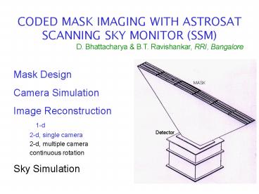
D. Bhattacharya B.T. Ravishankar, RRI, Bangalore
Mask Design Camera Simulation Image
Reconstruction 1-d 2-d, single
camera 2-d, multiple camera
continuous rotation Sky Simulation
MASK
Detector
2
CODED MASK IMAGING CONCEPT
Multiple pin-hole MASK Mask casts shadow on
detector plane Shift of shadow pattern encodes
source location Cross correlation of mask pattern
with shadow recovers shift and locates
sources Designed for pointed-mode observation
3
Mask Design Goals
1. Clean autocorrelation function (min.
sidelobes) 2. Maximum transparency (photon
collection)
Adopted
63-element pseudo-noise Hadamard Set URA Six
different patterns, one-dimensional coding Open
Fraction 50 Flat sidelobe response in cyclic
autocorretation
4
RANDOM URA
5
Six mask patterns for the SSM
Patterns joined side-by-side. Gives limited
resolution in non-coded direction
6
Camera Simulation
Set up Camera Geometry Set up source locations
(?x , ?y within FOV) Monte-Carlo simulate photon
strikes on mask Those striking open elements
propagated into the camera Photons striking the
shield discarded x-locations and wire nos.
recorded for those striking the detector Add
position uncertainties due to finite resoln. Add
background noise
7
Image Reconstruction (coding direction)
Bin detector counts at mask resolution Split FOV
into sky elements Identify detector and mask
sections for each sky elem Perform cross
correlation of detector counts with (a) mask and
(b) complement of mask Diff. (a)-(b) yields
source strength at that sky element Coding Noise
due to sky element cross-talk. Model and remove
iteratively
8
(No Transcript)
9
(No Transcript)
10
(No Transcript)
11
(No Transcript)
12
(No Transcript)
13
(No Transcript)
14
Image Reconstruction (2-d, single camera)
6 mask patterns, 8 wires 48 basic 1-d
reconstructions 55 allowed combinations of these
48 reconstructions correspond to different source
locations in the uncoded direction Look for max.
S/N among these 55 combinations, resulting in
recognition of source location in uncoded
direction Final resolution (nominal) 10 arcmin
x 2 deg Eventual refined 2-d location by using 2
cameras with crossed FOV
15
Reconstruction Raw
Coding Noise Removed
16
ASTROSAT SSM Coded Mask Development Present
Status
Mask Design Completed Camera Simulation
Software developed, documented.
Further refinements after
fabrication. Image Reconstruction 1-d
Basic software ready, including IROS.
Documentated. Richardson-Lucy evaluation
on. 2-d, single camera Capability
demonstrated. Effects of some
non-idealities investigated. 2-d,
multiple camera Not yet taken up
Continuous rotation Investigations started Sky
Simulation Not yet taken up
17
ASTROSAT SSM Coded Mask Development Next six
months (April- September 2002)
Finalise current version of imaging software and
complete documentation Finish evaluation of
Richardson-Lucy procedure Devise reconstruction
algorithms for continuously rotating camera.
Investigate alternative camera design. Begin
development of tools for Sky Simulation
Current person-power 11
18
Shadow Pattern Source location x-elem60,
y-elem27
Pattern 3
Pattern 4
19
(No Transcript)
20
Reconstruction Raw
Coding Noise Removed


![Consent for Research Study A study for patients diagnosed with locally advanced breast cancer Learning if the imaging agent, [18F] fluorothymidine (FLT), helps to predict the success chemotherapy treatment](https://s3.amazonaws.com/images.powershow.com/4538000.th0.jpg?_=20131024057)


