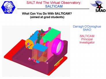
What Can You Do With SALTICAM - PowerPoint PPT Presentation
1 / 31
Title:
What Can You Do With SALTICAM
Description:
Spherical aberration corrector. SALT Layout at. Top of Telescope. Salticam. fold mirror ... The need for optics: mapping the field of view onto affordable ... – PowerPoint PPT presentation
Number of Views:25
Avg rating:3.0/5.0
Title: What Can You Do With SALTICAM
1
- What Can You Do With SALTICAM?
- (aimed at grad students)
Darragh ODonoghue SAAO SALTICAM Principal Invest
igator
2
Optical Layout at the Top of the Telescope
PFIS Slit Plane
SALTICAM
SALTICAM fold mirror
3
SALT Layout atTop of Telescope
RSS/PFIS
Salticam
Salticam
Salticamfold mirror
Spherical aberration corrector
Light fromprimary mirror
4
SALTICAM (in here)
SAC
5
SALTICAM Major Components
Optics
Cryostat detector
Filter jukebox
6
- Available filter sets
- UBVRI
- Sloan
- Stromgren
Up to 8 filters at a time
7
- THE 2 SALTICAM CCDs (at installation)
- 180 k of silicon
8
The need for optics mapping the field of view
onto affordable silicon
ScienceFoV(8 arcmin)
CCD1 CCD2
GuideStarFoV (outer 1arcmin)
9
Architecture of a single CCD
IMAGE AREA Frame Transfer
boundary STORE AREA
vertical clocking
vertical clocking
Split readout register
Readout Amp 1
Readout Amp 2
50 pix
50 pix
10
Typical SALTICAM Data Frame
Vignettingbycryostatwindow
Badcolumn
Amp2
Amp3
Amp4
Amp1
Bias/overscan strip foramps 2 3 physical
gap
11
Typical Applications
Colour-Magnitude Diagrams
GlobularclusterM5
12
Variability Studies SNe etc.
13
- Science Applications
- Supportive of programs on RSS/PFIS and other
facilities - Queue-schedule advantage variability
- High-time resolution
14
- What are the major considerations?
- Efficiency max shutter-open time andloss of
light in the instrument - Image quality for maximum contrast against the
background sky
15
Throughput
16
Throughput
17
- Technical Specifications/Details
- http//www.salt.ac.za/telescope/instrumentation/sa
lticam/
18
- Signal To Noise Calculations
- Signal
- Photons From Target
- Noise
- Photons From Sky underneath the target
- minimize by going for dark time
- minimize by best image quality (seeing)
- CCD detector readout noise
- minimize by using least number of pixels (by
prebinning) - S/N Target photons
- ___________________________________
_
19
- Signal To Noise Calculations for U B V R
I 20
20
- Gain and Readout Speed Considerations
- Gain
- Faint for the faintest targets
- Bright for brighter targets
- Readout Speed
- Slow less readout noise
- usual mode
- Fast more readout noise
- if you need the time resolution
21
For High Time Resolution (seconds)Frame
Transfer Operation Is Needed
At the end of each exposure, rapidly transfer the
image from the image section to behind the
mask section and read out during the next
exposure
22
- CCD Performance
23
Highest time Resolution astronomy 100
millisecond resolution studies of eclipses,
QPOs and other short timescale phenomena.
24
- Frame Transfer Mask in Slot Modefor 0.1 sec
sampling
Image/store area Split
Serial Readout Registers
25
- Frame Transfer Mask Slot Mode
26
Slot Mode Control
(a)
(b)
(c)
27
- Total cycle timewill be 0.10 or 0.25 sec.
Slot Mode Mask
Slot Mode Vignetting
28
RSS/PFIS highest time resolution slot similar to
SALTICAM
29
PFIS Fast Spectroscopy
- PFIS Slot mode
- Slot in telescope focal plane
- placed just above frame transfer
- boundary
- Do 2 x slot width row transfers
- (discard smeared rows)
- This example has 204 px slot
- (27 arcsec), each shifted 408
- rows at a time.
- Expect to run at gt76 msec integrations with 6
msec deadtime (row transfers) - fast spectroscopy
- fast spectropolarimetry
30
Driftscanning
Vertical clocking of rows at same rate star
drifts down chip
- 100 per cent shutter open time
- Tracker stationary
- Maximum primary mirror area
Horizontal clocking after each individual
vertical transfer
31
- Salticam Upgrade
- Minor fixes of mechanical issues
- Software upgrade
- Installation of autoguider
- Delayed due to the instrument being needed for
image quality investigation


