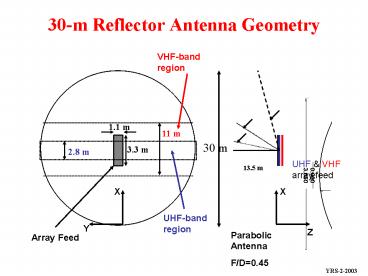
30m Reflector Antenna Geometry
1 / 20
Title:
30m Reflector Antenna Geometry
Description:
Dual-Band Low-Frequency Soil Moisture Radar: Array Feed. 30 meter ... to the limitations of the anechoic chamber at such low frequency. ... anechoic chamber at ... –
Number of Views:129
Avg rating:3.0/5.0
Title: 30m Reflector Antenna Geometry
1
30-m Reflector Antenna Geometry
VHF-band region
11 m
30 m
3.3 m
2.8 m
UHF VHF array feed
13.5 m
X
X
UHF-band region
Y
Z
Parabolic Antenna F/D0.45
Array Feed
YRS-2-2003
2
Dual-Band Low-Frequency Soil Moisture Radar
3.3m
1.1m
3
Dual-Band Low-Frequency Soil Moisture Radar
Array Feed
3-element patch array patterns at 137.5 MHz
H-port principal-plane patterns for probes 1,3
and 5
V-port principal-plane patterns for probes 2,4
and 6
4
30 meter Parabolic AntennaFreq137.5 MHz
H-Plane pattern
E-Plane pattern
Current on the reflector
YRS-2-2003
5
30 meter Parabolic AntennaFreq435 MHz
H-Plane pattern
E-Plane pattern
Current on the reflector
YRS-2-2003
6
3.65m Parabolic AntennaScaled Reflector Geometry
(Scale 30/3.65)
40.174 cm
Array Feed
X
X
Y
Z
Parabolic Antenna F/D0.33
Array Feed
YRS-2-2003
7
Existing 3.65m parabolic reflector antenna at JPL
to be used for scaled frequency measurements
YRS-2-2003
8
3.65 meter Parabolic AntennaFreq3.57 GHz
E-Plane
45o-Plane
H-Plane
Current on the reflector
YRS-2-2003
9
3.65 meter Parabolic AntennaFreq1.13 GHz
45o-Plane
E-Plane
H-Plane
Current on the reflector
YRS-2-2003
10
3.65 meter Parabolic Antenna
Freq3.57 GHz
Freq1.13 GHz
YRS-2-2003
11
DualFrequency Dual-Polarization Stacked Patch
Feed Design
U2
U1
L
GP
Top-view of Stacked Patch
Stacked patch built at Antenna Lab (UCLA) 1 and
2 are the feed points for lower patch 3,4,5 and
6 are the feed points for the upper patch
Side-view of Stacked Patch
Grid used in FDTD Simulation of Stacked Patch
YRS-2-2003
12
VHF / P-Band Stacked Patch Array
39.1 square
39.1 square
12.46 square
12.46 square
9.01
21.47
5 square hole
2.585
2.585
(0.791?o _at_ 435 MHz)
Dimensions for the scaled feed element
Lower patch frequency 1.13GHz Upper patch
frequency 3.57GHz Dimensions L 13.3 cm L1
12.0cm L2 3.9cm L3 2.7cm L4 0.8 cm L5
7.4cm Substrate thickness for lower patch
6mm Substrate thickness for upper patch 3mm
YRS-2-2003
13
Simulated Return-Loss for Stacked Patch
Grid used in FDTD Simulation
Bandwidth 20MHz
Bandwidth 80MHz
S11 result ( feed at lower patch)
S11 result ( feed at upper patch)
YRS-2-2003
14
S11 Measurement Results for Stacked Patch Array
Lower Patch
Upper Patch
Bandwidth 8MHz
Bandwidth 35MHz
S11 , S22 are the reflection coefficient values
measured at ports 1 and 2
S33 , S44 , S55 , S66 are the reflection
coefficient values measured at ports 3,4,5 and 6
YRS-2-2003
15
Simulated Radiation Pattern for Stacked Patch
Grid used in FDTD Simulation
Radiation pattern (feed at upper patch)
Radiation pattern (feed at lower patch)
YRS-2-2003
16
Measured Radiation Patterns for Stacked Patch
(Upper Patches)
Port 4
Port 3
Port 6
Port 5
YRS-2-2003
17
Comparison of Simulated and Measured Results at
Port 6
Performance of port 6 is not satisfactory.
YRS-2-2003
18
Accomplishments and Observations
- Dual-stacked patch configuration design has been
completed - Completed patch design for the scaled frequencies
of 1.13GHz and 3.57GHz - Evaluated and performed parametric studies
(return-loss, bandwidth and radiation pattern)
for the stacked patch array configuration using
the Finite-Difference Time Domain Method
(UCLA-FDTD code) - Completed building and measurement of the scaled
frequency feed element - Observations
- The simulated radiation pattern for the lower
patch shows a high back-radiation due to a small
ground plane (twice the substrate thickness is
required to account for fringing fields) - Measurements could not be performed due to the
limitations of the anechoic chamber at such low
frequency. - The S11 measurement results for the lower patch
have a narrower bandwidth than expected. We
believe it is because of the small diameter of
the flexible coaxial cable used for feeding the
patch - The far-field pattern at port 6 (refer to
picture) shows a very high cross-polarization
both in measurement and simulation. We need to
relocate port 6 similar to port 4 to make the
configuration symmetric and feed it out of phase
in an array configuration.
19
Future Goals for Array/Reflector Design
- Replace the small diameter flexible coaxial
cable with a thicker diameter rigid - cable for the lower patch
- Relocate port 6 to make the patch configuration
symmetric - Perform measurements for the rebuilt stacked
patch array at the new - anechoic chamber at UCLA or at JPL
- Perform elaborate study on the power-divider
network for feeding the array - Perform evaluation models for studying the array
with the feed network - Build the three element array with the feed
network and evaluate its - performance
- Integrate the measured array patterns with
reflector antenna analysis
20
UCLA Team Prof. Y. Rahmat-Samii K. Kona
(PhD student) M. Manteghi (PhD student) F. Yan
(Post Doc) J. Robinson (Undergrad student)
Publications 1 Keerti S. Kona and Yahya
Rahmat-Samii, Design and Analysis of a Novel
Probe-feeding method for Stacked Microstrip Patch
Antennas, IEEE AP-S Int. Symp.,Columbus, Ohio,
June 2003. 2 Keerti S. Kona and Yahya
Rahmat-Samii, Novel Probe-feeding Architectures
for Stacked Microstrip Patch Antennas, Annual
Research Review Symposium, 2002, UCLA


