High Level Telecom Architecture - PowerPoint PPT Presentation
1 / 4
Title:
High Level Telecom Architecture
Description:
Passive Optical Splitter. Home Run Copper. Battery. 2. Outside Plant Cable Topology - DLC ... Passive Fiber Splitter. To Central Office ... – PowerPoint PPT presentation
Number of Views:452
Avg rating:3.0/5.0
Title: High Level Telecom Architecture
1
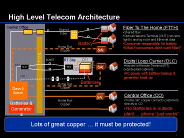
High Level Telecom Architecture
Central Office
MDF
Class 5 Switch
- Central Office (CO)
- home run copper connects customers directly to
CO - No Batteries in outside plant phone just
works
SAI
Home Run Copper
Batteries Generators
Lots of great copper it must be protected!
2
Outside Plant Cable Topology - DLC
F2 Aerial Cable
Remote Terminal
SAI/FDI
F1/F2 x-connect
Drop to House
DLC
F2 Buried Cable
Feeder (F1 Cable)
F1 Cable to CO is being retired as we speak
From Central Office
Losing Feeder cable to SAI cuts-off direct access
to customers from Central Office
3
Outside Plant Cable Topology - FTTH
F2 Aerial Cable
SAI/FDI
Drop to House (aerial or buried)
To Central Office
Feeder (F1 Cable)
Bandwidth is good but allowing this copper to
disappear is wrong and dangerous
4
Key Take Aways
- Fiber and Copper together provide best of all
worlds - Bandwidth
- Ubiquity
- Reliability
- All maintenance systems must be kept in operation
- All one network with different last mile
technologies - Feeder copper is already being retired
- What is going to happen to your feeder and drop
with FTTH? - Already being removed for aesthetic reasons!
Provision of Broadband must not negate National
Security and Emergency Preparedness

