GE Aircraft Engine Design Challenge - PowerPoint PPT Presentation
1 / 36
Title:
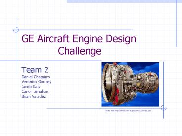
GE Aircraft Engine Design Challenge
Description:
GE Aircraft Engine Design. Challenge. Team 2. Daniel Chaparro. Veronica Godbey. Jacob Katz ... Modify an existing engine to obtain 36,000 lbf thrust for an ... – PowerPoint PPT presentation
Number of Views:160
Avg rating:3.0/5.0
Title: GE Aircraft Engine Design Challenge
1
GE Aircraft Engine Design Challenge
- Team 2
- Daniel Chaparro
- Veronica Godbey
- Jacob Katz
- Conor Lenahan
- Brian Valadez
Picture from http//cfm56.com/engines/cfm56-3/inde
x.html
2
Problem Statement
- Modify an existing engine to obtain 36,000 lbf
thrust for an aircraft and an SFC below 0.320
(lbm/hr)/lbf.
3
Analytical Approach
Picture from http//www.geae.com/services/material
/technologyupgrades/spotlight_cfm563.html
- Determining of Equations using Cycle Analysis
- Expandable Baseline Code
- Analysis and Redesign of Baseline code
- Implementation of Optimization code into the
Baseline Code - Analysis of Optimization Results
- Discussion of the Implications of the Results
4
Assumptions Concepts
- Ignoring changes of Kinetic Energy in all areas
except inlet, nozzle, and bypass flow - Ignoring shaft losses (perfect bearings used)
- Perfect combustion
- 1st Law
- 2nd Law
- Gibbs (combined 1st 2nd Laws)
- Conservation of Mass
- Conservation of Momentum
5
Cycle Analysis Equations
- Inlet, Fan and Bypass
- Booster and Compressor
- Area of a circle
- Bypass Ratio
- Pressure ratio relations
- Bypass Ratio
- Mass Continuity
- Adiabatic efficiency relations
- Stagnation/ Static relations with Mach number
6
Cycle Analysis Equations (cont.)
- Combustor
- High and Low Pressure Turbines
- Assume negligible changes in total pressure
- Energy balance/ Combustor efficiency relations
High Pressure Turbine
- Power balance Turbine work Compressor work
plus Losses
- Turbine efficiency relationship
- Power balance Turbine work Fan work plus
Booster work plus Losses
- Turbine efficiency relationship
7
Cycle Analysis Equations (cont.)
- Nozzle
- Engine Performance
- Thrust is equal change in momentum
- Total/ Static temperature and pressure relations
with Mach number
- Definition of speed of sound
- Definition of SFC
8
Baseline Calculations
- Wrote a MATLAB script to process the
aforementioned equations. - Relevant variables can be modified by the user or
another script. - Once corrected, the code produced expected
results
Picture from http//www.virtualservices.com.au/tes
timonials.htm
9
Part A Results
- Thrust 12,662 lbf
- SFC 0.3039 (lbm/hr)/lbf
- Does NOT meet requirements as standing alone
- Would require 3 engines to meet specs
Picture from http//www.eurostir.co.uk/eurostir_sn
ecma.html
10
Optimization
Picture from http//www.tsl.state.tx.us/ld/project
s/trc/2003/manual/clipart/celebrations/magglass.jp
g
- Baseline code used as basis for optimizing codes.
- Two approaches were used to model the engine
optimization process. - Why?
- Second opinion
- Sanity check
11
Optimization Code Logic
Picture from http//fromtheflightdeck.com/Stories/
turbofan/
- Find all possible solutions for each variable
over a logical range. - Inlet diameter
- BPR
- Fan pressure ratio
- Booster pressure ratio
- Turbine exit temperature
- 2. Run baseline simulation on each solution.
- 3. Pick solutions that lie within customer
requirements. - 4. Examine trends to find optimal solution in set
given by step 3.
12
(No Transcript)
13
(No Transcript)
14
(No Transcript)
15
(No Transcript)
16
(No Transcript)
17
(No Transcript)
18
(No Transcript)
19
(No Transcript)
20
(No Transcript)
21
(No Transcript)
22
(No Transcript)
23
(No Transcript)
24
(No Transcript)
25
(No Transcript)
26
(No Transcript)
27
(No Transcript)
28
(No Transcript)
29
(No Transcript)
30
(No Transcript)
31
Optimization Results
- Minimum Design
- Inlet diameter 59 inches
- BPR 5.55
- Fan pressure ratio 1.582
- Booster pressure ratio 3
- Thrust 18001 lbf
- SFC .2662
- However, Does not allow for any efficiency drop
32
Optimization Results
- Margin Design
- Inlet diameter 59 inches
- BPR 5.211
- Fan pressure ratio 1.53
- Booster pressure ratio 3
- At normal Efficiency
- Thrust 18487 lbf
- SFC .2783
- At 1 reduced Efficiency
- Thrust 18000 lbf
- SFC .2809
33
Optimized Customer Requirements
- Resulting Per Engine Statistics
- Thrust 18,001 lbf
- SFC 0.26624 (lbm/hr)lbf
34
What it all Means
Picture from http//www.tc.gc.ca/marinesafety/CES/
small-commercial-vessels/Passenger-Vessels/FAQ.htm
- Higher Thrust
- Only 2 engines needed for the aircraft, not 3!
- Weighs less
- Less maintenance
- Lower fuel costs
- Total thrust is
- 36,000 lbf
- Lower SFC
- Needs less fuel
- Range increased
- Carries effectively more fuel
- Runs at lower temperatures, thus prolonging blade
life
35
What it all Means (cont)
36
Conclusion
Picture from http//www.etailersdigest.com/celebra
te/refresh/
- Buy our engines!

