
AC i-V relationship for R, L, and C - PowerPoint PPT Presentation
1 / 5
Title:
AC i-V relationship for R, L, and C
Description:
Generalized Ohm's law VS(jw) = Z IS(jw) Everything we learnt before applies for phasors with generalized ohm's law. Capacitor Load ... – PowerPoint PPT presentation
Number of Views:27
Avg rating:3.0/5.0
Title: AC i-V relationship for R, L, and C
1
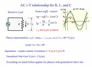
AC i-V relationship for R, L, and C
Source vS(t) Asinwt
Resistive Load
VR and iR are in phase
Phasor representation vS(t) Asinwt
Acos(wt-90) A ?-90VS(jw)
IS(jw) (A / R)?-90
Impendence complex number of resistance
ZVS(jw)/ IS(jw)R
Generalized Ohms law VS(jw) Z
IS(jw) Everything we learnt before applies for
phasors with generalized ohms law
2
Capacitor Load
ICE
VC(jw) A ?-90
Notice the impedance of a capacitance decreases
with increasing frequency
3
Inductive Load
ELI
Phasor VL(jw)A ?-90 IL(jw)(A/wL)
?-180 ZLjwL
Opposite to ZC, ZL increases with frequency
4
AC circuit analysis
- Effective impedance example
- Procedure to solve a problem
- Identify the sinusoidal and note the excitation
frequency. - Covert the source(s) to phasor form
- Represent each circuit element by its impedance
- Solve the resulting phasor circuit using previous
learnt analysis tools - Convert the (phasor form) answer to its time
domain equivalent.
Ex. 4.16, p180
5
Ex. 4.21 P188
R1100 W, R275 W, C 1mF, L0.5 H,
vS(t)15cos(1500t) V. Determine i1(t) and
i2(t). Step 1 vS(t)15cos(1500t), w1500
rad/s. Step 2 VS(jw)15 ?0 Step 3 ZR1R1,
ZR2R2, ZC1/jwC, ZLjwL Step 4 mesh equation