
Link Layer: Motivation - PowerPoint PPT Presentation
1 / 29
Title: Link Layer: Motivation
1
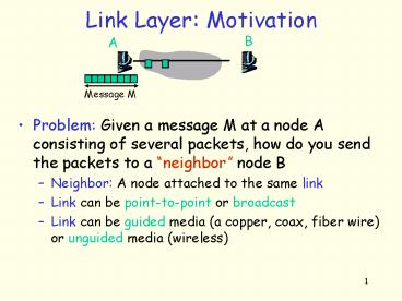
Link Layer Motivation
B
A
Message M
- Problem Given a message M at a node A consisting
of several packets, how do you send the packets
to a neighbor node B - Neighbor A node attached to the same link
- Link can be point-to-point or broadcast
- Link can be guided media (a copper, coax, fiber
wire) or unguided media (wireless)
2
Link and Physical Layers
- This communication problem is handled by 2
protocols - A Link Layer (LL) that sits on top of the
physical layer (PL) and deals with - Packet Encapsulation, Mux/Demux
- Framing Detecting frame boundaries
- Error Detection/Recovery Detecting corrupt
frames - Media Access Control (if the link is multi-access
or broadcast) - Reliable delivery, flow control? Optional
- A Physical Layer (PL)
- deals with encoding/decoding bits of a frame
to/from the link
3
Network Interface Card (NIC)
- LL in part, PL in total are implemented in NIC
- Ethernet card, 802.11 card,
- NIC is semi-autonomous
- Listens to the link independent of the CPU
- Talks to CPU after reception of a new frame
- CPU talks to the card to send a frame
- Has connectivity to both the I/O bus and the
network link
4
Link Layer Service Interface
- Every Link Layer must export a service interface
to the layers on top of it - Unreliable frame service
- Corrupt frames are not recovered, frame sending
order may not be preserved - OK when error rate is low so packet recovery is
left to upper layers Most wired links are of
this type - Reliable, unordered frame service
- Corrupt frames are recovered, frame sending order
may not be preserved, also duplicate packets
possible? - Good for links where the error rate is high such
as wireless links - Reliable, ordered frame service
- Corrupt frames are recovered, frames are
delivered in the order they were sent, no
duplicate frames possible. - Very restrictive! X.25 links used this model
5
Steps in Transmission of a Datagram to a Neighbor
Datagram
Datagram
H
Datagram
Y
All bits in D OK?
LL
N
Datagram
H
Detected error
LL
D
EDC
Datagram
H
EDC
Decode Bits from the Link
Encode Bits to the Link
PL
PL
6
General LL Frame Format
- All LL headers must contain a mux/demux key
(Type) - Type field in LL header specifies upper layer
protocol - IP is one of many upper layer protocols (IPX,
AppleTalk, ARP, ) - Each LL defines its own protocol type numbering
for upper layers - LL header might also contain some control fields
- Does the LL require reliable delivery, flow
control - In a broadcast link, header contains the source
and destination MAC addresses
7
Upper layer protocol numbersin Ethernet
- http//www.cavebear.com/CaveBear/Ethernet/type.htm
l - Some Ethernet protocol types
- 0800 DOD Internet Protocol (IP)
- 0806 Address Resolution Protocol (ARP)
- 8037 IPX (Novell Netware)
- 80D5 IBM SNA Services
- 809B EtherTalk (AppleTalk over Ethernet)
8
Maximum Transfer Unit (MTU)
- Each LL has a limit on the max. LL frame size
- This limit is called the Maximum Transfer Unit
MTU of the link - MTU is the maximum frame size including the LL
header, trailer etc. - If a higher layer protocol such as IP wants to
send a datagram bigger than the LL MTU, it has to
break the datagram into smaller pieces
(fragments), so that each fragment is smaller
than the MTU - This is called fragmentation (at the sender) and
de-fragmentation (at the receiver)
9
Error Detection/Correction
- Errors caused by signal attenuation, electrical
interference or thermal noise. - Receiver detects presence of errors, take an
action - Possible actions
- Correct bit errors if possible and continue
- Signal sender for retransmission (X.25)
- Drops frame Most common (PPP, Ethernet, )
10
Error Detection/Correction General Idea
- To detect and correct errors, we add extra error
detection and correction bits (EDC) to the frame
- D Data protected by error checking may
include header fields - Error detection not 100 reliable!
- protocol may miss some errors, but rarely
- larger EDC field yields better detection and
correction
11
Error detection/correction
Error Detection/Correction
Parity Checks
Checksum
Cyclic Redundancy Checks
12
Checksums
- Receiver
- compute checksum of received segment
- check if computed checksum equals checksum field
value - NO error detected
- YES no error detected. But maybe errors
nonetheless? - Mis-ordered words
- Sender
- treat segment contents as sequence of 16-bit
integers - checksum addition (1s complement sum) of
segment contents
- Why use checksum?
- simple to implement in software
- Typically used by upper layer protocols TCP,
UDP, IP.. - Found to be enough in ARPANET by experience
13
IP Checksum Algorithm
- unsigned short IPCheckSum(unsigned short buf,
int count) - register unsigned long sum 0
- while (count--)
- sum buf
- if (sum 0xFFFF0000)
- / carry occured, so wrap around /
- sum 0xFFFF
- sum
- //end-if
- //end-while
- return unsigned short((sum 0xFFFF))
- //end-IPCheckSum
14
Parity checking
- Single Bit Parity
- Add an extra bit to a 7-bit code to balance the
of 1s in a byte - Odd parity sets the 8th bit to 1 to give an odd
of 1s in the byte - Even parity sets the 8th bit to 1 to give an
even of 1s in the byte - Detect single bit errors
- Two Dimensional Bit Parity
- Computes parity for each bit position across
each of the bytes contained in the frame - This results in an extra byte for the entire
frame in addition to a parity bit for each byte - Detect and correct single bit errors
parity bit
7 data bits
parity bit
1
0 1 0 1 0 0 1
7 data bits
0
1 1 0 1 0 0 1
1
Data
0 1 0 1 0 0 1
1
1 0 1 1 1 1 0
Even parity example
1
0 0 0 1 1 1 0
Parity Byte
1
0 0 1 0 0 0 0
15
Two-Dimensional Parity Checking
16
Cyclic Redundancy Checks (CRC)
- Idea
- We have a n-bit message M to send
- Treat message bits as coefficients of n-bit
polynomial (n-1 degree polynomial) M(x) - Append r bits called the CRC-bits to the end of
the message such that the new message M of
length nr-bits is divisible by a generator
polynomial G(x) - G(x) is well known and agreed upon in advance
- CRC-16 x16 x15 x2 1 (used in HDLC)
- CRC-CCITT x16 x12 x5 1
- CRC-32 x32 x26 x23 x22 x16 x12 x11
x10 x8 x7 x5 x4 x2 x 1 (used in
Ethernet) - Send M(x), which is divisible by G(x), to the
receiver
17
Cyclic Redundancy Checks (CRC)
- Given n-bit message M, how to compute M of
length nr-bits? - Think of n-bit message M as being represented by
a n-1 degree polynomial, where the value of each
bit (0 or 1) is the coefficient for each term in
the polynomial. - E.g., the message M(x) 10011010 corresponds to
the polynomial x7 x4 x3 x - Consider the generator polynomial G(x) of degree
k - Suppose G(x) x3 1. In this case k 3.
- Multiply M(x) by xk to obtain P(x) of degree
n-1k - Do polynomial division of P(x) by G(x) to obtain
remainder R(x) - Add R(x) to P(x) to obtain M(x)
- Notice that M(x) is divisible by G(x), i.e., the
remainder is 0
18
Example CRC Computation
- Data
- 101110
- Generator Polynomial
- x3 1 (1001)
- Send
- 101110011
Data
R
19
CRC - Receiver Algorithm
- Assume that the receiver received T(x) of length
nk-1 bits. What does the receiver do with this
message? - Assume T(x) M(x) E(x)
- Divide T(x) by G(x) to obtain the remainder R(x)
- If R(x) is 0, two things are possible
- There is no error in the message, i.e., E(x) 0
- E(x) is divisible by G(x)
- A clever choice of G(x) can make the second case
extremely rare so that we can safely conclude
that an R(x) 0 result means that the message is
error free and non-zero means that an error has
occurred
20
Forward error correction
- FEC
- Use error correcting codes to repair losses
- Add redundant information which allows receiver
to correct bit errors - Requires knowledge at information and coding
theory and is out of the scope of this course
21
Framing
- Up until now, we have added LL header to the data
and appended a EDC to the end to form a LL frame - This frame will be transmitted to the destination
(receiver) - Problem How would the receiver determine where
the frame bits start and where they end as the
adapter is receiving a sequence of bits from the
link? - Called the framing problem
- Idea Add some extra framing information before
sending the frame
22
Framing
- Several solutions exist to solve the framing
problem. We will look at a few - Byte counting Approach DDCMP
- Before sending the frame bits, send of bytes in
the frame first - Sentinel Approach - BISYNC, IMP-IMP, HDLC, PPP
- Denote the end (and maybe the beginning) of the
frame by a special char, called the sentinel char
or flag - Q What if the sentinel char appears in the data?
- Byte stuff the control chars
- Bit stuff data sequence
- Physical Layer Coding Violations Ethernet, 802
LANs - Make use of physical layer. Use an encoding
sequence that is not used for encoding data to
mark the end of a frame - Requires a dependence between LL PL
23
Byte-Counting Approach DDCMP
8
8
8
16
42
14
Body (variable size)
DDCMP frame format
- Count specifies the size of the frame body
- Problem What if a transmission error corrupts
the count field? - Solution
- Collect as much data as the count field, do a
CRC. If the CRC is bad, then discard the frame
and wait until the next SYN char to start
collecting the bytes for the next frame - Resynchronization can fail if start of frame
character is inside packets as well BUT will
eventually sync up - Not a very popular technique
24
Sentinel Approach PPP
8
16
8
Body (variable size)
PPP frame format
- Each frame starts and ends with the sentinel char
0x7e - Uses byte-stuffing to solve the problem of 0x7e
appearing inside the body - Sender
- Adds (stuffs) extra lt 01111101gt 0x7d byte
before each lt01111110gt 0x7e data byte - 0x7d is also escaped with a 0x7d
- Receiver
- Two 01111101 0x7d bytes in a row discard first
byte, continue data reception - 0x7d followed by 0x7e discard first byte,
continue data reception - Single 01111110 0x7e flag byte End of frame
25
Byte Stuffing in PPP Example
26
HDLC Bit Stuffing
Body (variable size)
0x7e
0x7e
HDLC frame format
- Each frame starts and ends with the sentinel char
0x7e (0x01111110) - When the link is idle, 0x7e is transmitted to
keep the clocks synchronized - Uses bit-stuffing to solve the problem of 0x7e
appearing inside the body - Sender
- A 0 bit is stuffed after any 5 consecutive 1s,
i.e., 11111 - Receiver
- After reception of 5 consecutive 1s, examine the
6th bit - If 6th bit is 0, remove it (stuffed bit)
- If 6th bit is 1 and 7th bit is 0 (end of frame)
- If 6th bit is 1 and 7th bit is 1 (sender is
indicating an abort condition)
27
Bit-Stuffing in HDLCExample
28
Physical Layer Coding Violations
- Make use of physical layer encoding scheme.
- Use an encoding sequence that is not used for
encoding data to mark the end of a frame - Only applicable to links in which the encoding on
the physical medium contains some redundancy - Used by Ethernet and IEEE 802 LANs
- No need for byte/bit stuffing (not even length
field!) - More efficient use of link bandwidth
- But, requires a dependence between LL PL
- LL requires a specific PL to run.
- Thats why Ethernet and IEEE LAN specs combine LL
and PL specs together
29
Recap
- Up until now, we have a NL datagram coming into
to LL - LL adds LL header (H)
- Done in software
- LL computes EDC
- Hardware (Ethernet) or Software (PPP)
- LL adds framing info (if necessary)
- Hardware or Software (PPP)
- PL encodes the bits to the link
- Hardware
- This algorithm is enough for a point-to-point
link. - What about broadcast links?
- Next
Recommended
CrystalGraphics Presentations


