Chap 2. Operational amplifiers (op-amps) - PowerPoint PPT Presentation
1 / 13
Title:
Chap 2. Operational amplifiers (op-amps)
Description:
Avo = infinity (Avo is the open-loop gain, sometimes A or Av of the op-amp) ... To analyze an op-amp circuit. Write node equations at and - terminals (I = I- = 0) ... – PowerPoint PPT presentation
Number of Views:100
Avg rating:3.0/5.0
Title: Chap 2. Operational amplifiers (op-amps)
1
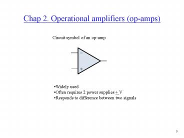
Chap 2. Operational amplifiers (op-amps)
Circuit symbol of an op-amp
- Widely used
- Often requires 2 power supplies V
- Responds to difference between two signals
2
2.2 Ideal op-amp
- Characteristics of an ideal op-amp
- Rin infinity
- Rout 0
- Avo infinity (Avo is the open-loop gain,
sometimes A or Av of the op-amp) - Bandwidth infinity (amplifies all frequencies
equally)
3
Model of an ideal op-amp
I
V
Vout A(V - V-)
I-
V-
-
- Usually used with feedback
- Open-loop configuration not used much
4
Summary of op-amp behavior
Vout A(V - V-) Vout/A V - V- Let A
infinity then, V -V- 0
5
Summary of op-amp behavior
V V- I I- 0
Seems strange, but the input terminals to an
op-amp act as a short and open at the same time
6
To analyze an op-amp circuit
- Write node equations at and - terminals (I
I- 0) - Set V V-
- Solve for Vout
7
2.3 Inverting configuration
Very popular circuit
8
Analysis of inverting configuration
I2
I1 (Vi - V- )/R1 I2 (V- - Vo)/R2 set I1 I2,
(Vi - V-)/R1 (V- - Vo)/R2 but V- V 0 Vi /
R1 -Vo / R2 Solve for Vo Vo / Vi -R2 / R1
I1
Gain of circuit determined by external components
9
2.4 Applications of the inverting configuration
Current in R1, R2, and R3 add to current in
Rf (V1 - V-)/R1 (V2 - V-)/R2 (V3 - V-)/R3
(V- - Vo)/Rf Set V- V 0, V1/R1 V2/R2
V3/R3 - Vo/Rf solve for Vo, Vo -Rf(V1/R1
V2/R2 V3/R3) This circuit is called a weighted
summer
10
2.5 Noninverting configuration
(0 - V-)/R1 (V- - Vo)/R2 But, Vi V V-, ( -
Vi)/R1 (Vi - Vo)/R2 Solve for Vo, Vo
Vi(1R2/R1)
11
Input resistance of noninverting amplifier
Rin Vin / I, from definition Rin Vin /
0 Rin infinity
V-
I
Vout A(V -V-)
V
12
Input resistance of inverting amplifier
Rin Vin / I, from definition I (Vin -
Vout)/R I Vin - A (V - V-) / R But V
0 I Vin - A( -Vin) / R Rin VinR / Vin
(1A) As A approaches infinity, Rin 0
I
V-
V
Vout A(V - V-)
13
Summary of op-amp behavior
Inverting configuration
Noninverting configuration
Vi
Rin 0 at this point
Vo/Vi 1R2/R1 Rin infinity
Vo /Vi - R2/R1 Rin R1


