HSI Course - PowerPoint PPT Presentation
1 / 28
Title:
HSI Course
Description:
Dr. Richard B. Gomez, Instructor. George Mason University ... Interferometer-Based Systems. Michelson Interferometer. Fourier Transform Interferometer System ... – PowerPoint PPT presentation
Number of Views:47
Avg rating:3.0/5.0
Title: HSI Course
1
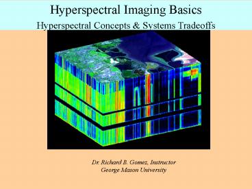
Hyperspectral Imaging Basics Hyperspectral
Concepts Systems Tradeoffs
Dr. Richard B. Gomez, Instructor George Mason
University
2
Outline
- Hyperspectral Concepts System Tradeoffs
- Signal-to-Noise Ratio (SNR)
- Spectral Resolution, Sampling Interval, Range
- Image Acquisition Mode Tradeoffs
- Data Collection Systems
- Classification of Hyperspectral Imaging Systems
- Ground, Airborne, Spaceborne
3
Radiometric Quantities
Quantity Radiant Energy (J) - Q Radiant Energy
Density (J/m3) U Radiant Flux (W) Power
P Radiant Exitance (W/m2) M Irradiance (W/m2)
E Radiance (W/m2-sr) L Radiant Intensity (W/sr)
I
Definition ?Pdt dQ/dV dQ/dt dP/dA dP/dA d2P/dAd?
dP/d?
4
Space Reference System
5
Basic Components of Remote Sensing System
- Energy Source
- Transmission Path
- Target
- Background
- Sensor
6
Hyperspectral Imaging General Concept
7
Hyperspectral Reflectance Measurements
8
AURORA Hyperspectral Image of Hawaii, Courtesy of
APTI, Inc.
9
Hyperspectral Signatures
10
Object Information Derived From Signal
11
Atmospheric Effects (Richards Fig. 2.1)
12
Atmospheric Compensation (continue)
13
Incident Radiation
- Incident Radiation Reflected Radiation
- Scattered Radiation
- Absorbed Radiation
- Transmitted Radiation
14
Upward Radiance Components
- L L1 L2 L3 L4
- L1 Path Radiance independent of surface
reflectance - L2 Attenuated Signal depends only on the
surface reflectance in the field of view.
Provides Surface information. - L3 Scattered by atmosphere to the surface and
reflected to the sensor. Affected by
non-Lambertian surface light. - L4 Light radiance reflected by the surface
with at least one scattering in the atmosphere
before reaching the sensor. Affectedby
nonuniform surface and by non-Lambertian surface
reflectionthat may be out of the field of view
of the sensor.
15
Total Radiance Available to Sensor
- Total Irradiance EG at Earths Surface
- EG E??T?cos ? ?? ED (Path Irradiance
ED) - The Radiance LT Due to Global Irradiance EG of
the pixel - LT (R/?)E??T?cos ? ?? ED
- Total Radiance Available to Sensor
- LS (RT?/?)E??T?cos ? ?? ED LP
- See John Richards Book Page 42, Equation 2.4
16
John Richards Equations
17
John Richards Reflectance Calculation
18
Basic System Capabilities
- Field-of-View (FOV) or Swath Width on the Ground
- Spectral Range
- Spectral Sampling Interval
- Spectral Resolution
- Spatial Resolution or Instantaneous FOV or
Ground Sample Distance (GSD) - Dynamic Range or Signal-to-Noise Ratio (SNR)
- Wavelength (Spectral) Calibration
- Radiometric Calibration
- Geometric Calibration
- Figure-of-Merit (indicator of overall system
performance)
19
Mission Requirements
- Mass
- Power
- Data Rate
- Altitude
- Ground Coverage
- Timeliness
- Speed (Ground Velocity)
- Platform Stability (Pointing Ability)
- Orbit Characteristics (Inclination, Offset,
Type, etc.) - Costs
20
System Parameters
- Mass
- Power
- Data Rate
- Encoding Level
- Spectral Discrimination
- Integration Time
- Detector Technology (Focal Plane Array, Format,
Pixel Size) - Pixel Pitch
- Focal Ratio or F-Number
- Focal Length
- Aperture
- Etendue
21
Linewidth Full Width at Half Maximum
Airborne Hyperspectral Systems
22
Classification of HSI Systems
- Image Acquisition Modes
- Whiskbroom Imagers
- Pushbroom Imagers
- Staring Imagers
- Spectral Selection Modes
- Dispersion Element (grating, prism)
- Filter-Based Systems
- Interference Filters
- Acoustical-Optical Filters
- Liquid Crystal Tunable Filters (LCTF)
- Interferometer-Based Systems
- Michelson Interferometer
- Fourier Transform Interferometer System
- Other (e.g., Multi-order etalons)
23
Image Acquisition Mode Tradeoffs
24
Spatial versus Spectral Resolution Tradeoffs
25
Spatial versus Spectral Resolution Tradeoffs
26
Principle Calibration Needs
- Geometric imaging aspects scan jitter,
platform motion - Relative geometric calibration FOV, IFOV, SSI
- Absolute geometric calibration GPS, INS, DTED
- Spectral (wavelength) spectral response of
each channel - Atomic emission line spectra spectral matching
- A-prior knowledge of sensor spectral
characteristics - Radiometric spectral radiance response
- Input radiance versus output digitized signal
- Dynamic range, quantization level, RMS noise
level
27
Radiometric System Parameters
28
Absorption Lines
When light from a luminous source passes through
a gas, the gas may extract certain specific
energies from the continuous spectrum. We then
see dark lines where the energy has been removed.
These dark lines are called absorption lines.


