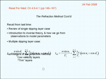
The Refraction Method Contd
1 / 9
Title:
The Refraction Method Contd
Description:
Review of single dipping layer case. Introduction to inverse theory, & how we go from ... V2 from slope of the line fit. At each geophone i calculate thickness as ... –
Number of Views:27
Avg rating:3.0/5.0
Title: The Refraction Method Contd
1
04 Feb 2008
Read For Wed Ch 4.0-4.1 (pp 149167)
The Refraction Method Contd
- Recall from last time
- Review of single dipping layer case
- Introduction to inverse theory, how we go from
- observations to model parameters
- Multiple dipping layer case
- Limitations of the refraction method
- Low velocity layers
- Thin layers
2
What if velocity changes within layers?
V1 2000 m/s
V2 1000 m/s
m 1/V1
m 1/V2
m 1/V2
m 1/V1
3
V1 500 m/s
V2 2000 m/s
V3 1000 m/s
m 1/V2
m 1/V3
m 1/V3
m 1/V2
m 1/V1
m 1/V1
4
What if the layer interface is not planar?
A
B
V1 500 m/s
z
V2 2000 m/s
m 1/V2
m 1/V2
m 1/V2
m 1/V2
m 1/V1
m 1/V1
5
A
B
V1 500 m/s
z
V2 2000 m/s
Basically have a difference in the intercept
times at one part of the line versus the other
6
Refraction from an irregular surface Delay-Time
Method
y
G
E
hE
V1
A
B
V2
Define delay time as the time the ray traveled in
layer 1 along a slant path less the time it
would have taken to travel the horizontal
distance (AB) at velocity V2. The total delay
time ?EG traveling from E to G (or G to E) is
where tR is total travel time. Delay time
under E is
7
Using trigonometry and Snells law for critical
angle,
We cant measure directly, but with reversed
shots
G
E
H
hE
V1
A
B
V2
?H from E ?H from G, and
8
Refraction from an irregular surface Delay-Time
Method
y
x
H
G
E
V1
V2
Problem however to get hH from ?H, must know
V2! But can also write (? a line with slope
2/V2!)
9
2
1
i
V1
V2
- Sometimes also called the plus-minus method
- Plot t1it2i vs xi for SP1, 2 and all geophones
i. Calculate - V2 from slope of the line fit.
- At each geophone i calculate thickness as


