
CASE 1830 Uni-Loader Service Repair Manual Instant Download (Part Number 9-73487)
Title:
CASE 1830 Uni-Loader Service Repair Manual Instant Download (Part Number 9-73487)
Description:
CASE 1830 Uni-Loader Service Repair Manual Instant Download (Part Number 9-73487) –
Number of Views:0
Title: CASE 1830 Uni-Loader Service Repair Manual Instant Download (Part Number 9-73487)
1
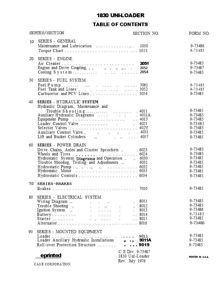
1830 UNI-LOADER TABLE OF CONTENTS SECTION NO.
SERTES/SECTION
FORM NO.
10
SERIES - GENERAL Maintenance and Lubrication
.............,. 1050 Torque Chart ...... ......
.... ... .... .. . 1051
9-73486 9-73485
20 SERIES - ENGINE Air Cleaner ...................
....... 2051
9-73485 9-73487 9-73485
Engine and Drive Coupling, , , ,. , ,. ,, , . 2052
Cooling System........... . ... ...... 2054
30 SERIES - FUEL SYSTEM Fuel Pump........ ... . ..
.. . ..... 3061
9-73485 9-73485 9-73485
Fuel Tank and Lines . . . .... ... ... . 3052
Carburetor and PCV Lines ................. 3054
40 SERIES - HYDRAULIC SYSTEM Hydraulic Diagram,
Maintenance and Trouble Shooting........... .....
.. . 4011
9-73485 9-73485 9-73485 9-73485 9-73485 9-73485 9-
73485
Auxiliary Hydraulic Diagrams .... . . . 4011A
Equipment Pump ................... .. 4013
Loader Control Valve .......... . . 4021
Selector Valves ........................ 402'f
Auxiliary Control Valve .. Llft and Bucket
Cylinders
.. .. .. . . 4031 ... . .. .... 4057
60 SERIES - POWER DRAIN Drive Chalns, Axles and
Cluster Sprockets .. . 6023
9-73485 9-73485 9-73485 9-73485 9-73485 9-73485 9-
73485
Wheels and Tires . . . . . . . . . . . . . . . .
6024
Hydrostatic System and Operation .. .. 6030
Trouble Shooting, Testing and Adjustments
... 6031
Hydrostatic Pump . .. .. . .., ... ....... ..
.. 6032
Hydrostatic Motor ......................
6033 Hydrostatic Controls .....................
6034
70 SEBIES-BRAKES Brakes ..........................
.... 7010 80 SERIES - ELECTRICAL SYSTEM
9-73485
9-73485 9-73485 9-73486 9-73485 9-73485 9-73486
. . ..
. 8011 .. 8012
Wiring Diagram ... Trouble Shooting .. Ignition
System ... Battery .........
. . ...
. . ..... . . ..... .
. 8013
.. 8014
Starter ........ . , .... . .. 8015
Alternator ............................ 8016
90
SERIES - MOUNTED EQUIPMENT
9-73485 9-73485 9-73485
Loader ..................... . ..... 9011
Loader Ancillary Hydraulic Installations ,. .
, 9011A Roll-over Protection Structure
....... . . . . 9019
C E Div. 9-73487 1830 Unl-Loader Rev. July 1976
eprinted CASE CORPORATION
2
Section
MAINTENANCE AND LUBRICATION
G.E. Div. 9-73486 1830 Uni-Loader Rev. July 1976
CASE CORPORATION
3
1050-2
MAINTENANCE CHART
INTERVAL SERVIG E INSTRUCTIONS
Run-In Period After First 2 Hours Check fan belt tension, Torque wheel nuts to 80-90 foot-pounds every 2 hours until stable. Section 8016.
Every 10 Hours or Daily, Which- ever Occurs First Check engine oil level. Gheck radiator coolant level and check radiator for obstructions.
Grease loader pivot points.
Grease attachment pivot pomts.
Clean air cleaner dust cup and precleaner. Section 2051.
Fill fuel tank.
Visually check machine for broken, missing or loose parts. Check for leaks under machine.
Every 50 Hours or Weekly, Which- ever Occurs Flrst Check lan belt tension. Check battery Ouid level. Section 8016. Section 8014.
Check tire pressure. Section 6024.
Check hydraulic oil level. OH MUST be cold. Section 4011.
Grease control lever cross shaft.
Change engine oil.
Everyl00 Hours Change engine on filter, Check engine speeds. Clean out spark arresting mufoer (if so equipped), Section 2052.
Every 200 Hours Check drive chain tension. Section 6023.
Every 250 Hours Clean exterior of engine. Replace the points and spark plugs, Replace in-lie fuel filter. Inspect ignition wires and connections. Section 8013, Section 3052.
4
https//www.ebooklibonline.com Hello dear
friend! Thank you very much for reading. Enter
the link into your browser. The full manual is
available for immediate download. https//www.ebo
oklibonline.com
5
1050-3
INTERVAL SERVICE INSTRUCTIONS
Every 250 Hours Cont'd Adjust engine ya1ye tappets. Section 2052
Every 500 Hours of Operation Clean radiator fins and check for leaks. Glean and repack grease on cham coupler. Section 2052
Every 1000 Hours of Operation or Yearly Change hydraulic oa and oil filter, Clean hydraulic reservoir breather, Section 4011.
Every 2000 Hours of Operation or Yearly Drain, flush and refill chain compartment oil (each side), Drain, ftush and refill cooling system. Drain sediment and water from fiiel tank. Section 6023
as Required Glean or replace air cleaner element when red band on restriction indicator remains in view, Replace hydraulic oil filter. Torque wheel nuts to 80-90 foot-pounds every two hours until stable after reinstalling wheels, Check operation of steering controls, adjust as required, Drain sediment and water from fuel tank and change in-line fuel filter. Section 2051, Section 4011.
Rev. July 1976
6
1050-4
FLUIDS AND LUBRICANTS
G OMPON ENT CAPACITY U.S. Metric CAPACITY U.S. Metric SPECIFICATIONS
Fuel tank 14.5 gallons 55 liters Use leaded type regular gasoline.
Engine crankcse o1l W1th fiRer change 3paNs 2.8 liters Use Case HDM Oil - API classifi- cation SC and SD.
Without filter change 2.75 quarts 2.6 liters Above 32 F (0 G) ----SAE 30 10to 50 F (-12 to 10 C) ----SAE 20W20 Below 32 F (0 C) ---- SAE 10W Alternate oil Case l0W40
Equipment/trans- mission hydraulic system Total system Reserrolr refill 8 gallons 6 gallons 30 liters 22. 7 liters Use Case TPH Fluid Alternate oil Type C-2 transmission and hydraulic fluld such as Tenneco Hymans Fluld.
Battery As required As required Add colorless, odorless drinking water.
Grease fittings As required As required Above 32 F (0 C) Multipurpose or No. 2 lithium-soap base grease. Below 32 F (0 C) Multipurpose or No. 1 lithium-soap base grease.
Chain drive coupling As required As required Molykote, type G grease.
Cooling system 8 quarts 7.6 ltters Ethylene glycol and water should be mtxed for prevailing temperatures. Follow the manufacturer's specifi- cations.
Chaln compartments each side 4 quarts 3.8 11ters Use engine oil with API classifica- tion SD (MS) SAE 30.
7
Section
TORQUE CHART
Burl. Form 973485
Aug. 1974
CASE CORPORATION
8
1051-2 U.S. AND METRIC TORDUE SPECIFICATIONS Grad
e S Bolts, Nuts and Studs (Dry Threads)
N m 319-386 366-447
Thread size 1/4"-20 NC 1/4"-28 NF 5/16"-18
NC 5/16-24 NF
Ft-lbs 5-10 10-15 15-20 15-20
N m 7-13 13-20 20-27 20-2T
Thread size 3/4-10 NC 3/4-16 NF
Ft-lbs 235-285 270-330
7/8"-9 NC 7/8"-14 NF
360-440 395-490
488-597 536-664
18 NC 1"12 NF 1-1/8"-7 DC 1 -1/8"-12 NF
520-640 575-705 T20-820 790-970
705-867 780-955 976-1111 1071-1315
3/8-16 NC 3/8-24 NF
25-35 30-40
34-47 41-54
7/1614 NC T/1620 NF
4555 5060
61 74 6881
1-1/4"-7 NC l -1/4"-12 NF 1-3/8"-6 NC 1-3/8-12
NF 1-1/2-6 NC 1 -1/2-12 NF
1010-1240 1115-1365 1315-1610 1510-1850 1745-2135
1880-2420
1370-1681 1512-1850 1T83-2182 2047-2508 2366-2894
2549-3281
1/2"-l3 NC 1/2-20 NF 9/16-12 NC 9/16-18
NF 5/8"-l1 NC 5/8-18 NF
65-85 80-100 100-120 110-130 135-165 160-200
88-115 109-135 135-163 149-176 183-223 216-271
Grade 8 Bolts, Nuts and Studs (Dry
Threads) Ft-lbs N m Thread size Ft-lbs
N m 461-569 515-623 732-894 807-982
Thread size
1/4"-20 NC 1/4-28 NF
10-15 15-20
13-20 20-27
3/4"-10 NC 3/4-16 NF
340-420 380-460 540-660 595-725
5/16-18 NC 5/16"-24 NF
20-30 25-30
2f-40 34-40
7/8-9 NC 7/8"-14 NF
1-8 NC 1"-12"NF l -1/8"-7 NC 1 -1/8"-12 NF
810-990 900-1100
1098-1342 1220-1491
3/8"-16 NC 3/8"-24 NF
40-50 45-55
54-67 61-74
T/16-14 NC 7/16-20 NF 1/2-13 NC 1/2"-20
NF 9/16"-12 NC 9/16-18 NF 5/8"-11 NC 5/8-18 NF
60-80 70-90 100-120 110130 135-165 155190 200-24
0 215-265
82-102 95-122 136-162 149-176 183-223 210-257 2T1-
325 292-359
11501400 1295-1585
15591898 1756-2148
1-1/4-7 NC 1-1/4-12NF 1-3/8-6 NC 1-3/8-12
NF 1-1/2"-6 NC 1-1/2-12 NF
1640-2000 1800-2200 2140-2620 2450-3000 28453475
3200-3900
2224-2711 2440-2982 2901-3552 3322-4067 3857-4711
4339-4880
740313
9
1051-3 U.S. AND METRIC TORQUE SPECIFICATIONS Hydr
aulic Fittings (Steel)
37 Flare Torque
Dash Size
Tube O.D. Hose I.D.
Thread Size
Straight Thread O-ring Torque
Ft-lbs N m Ft-lbs N m
4 1/4" 7/16"-20 6-12 8-16 12-19 16-25
5 5/16" 1/2-20 8-16 11-21 1 6-25 22-33
6 3/8" 9/16-18 10-25 14-33 25-40 34-54
8 1/2" 3/4"-16 15-42 20-56 42-67 57-90
10 5/8 7/8"-14 25-58 34-78 58-92 79-124
12 3/4" l -1/16-12 40-80 54-108 80-128 108-174
14 7/8" 1-3/16-12 60-100 81-135 100-160 136-216
16 1" 1-5/16-12 75-117 102-158 117-18T 159-253
20 1 -1/4" 1-5/8-12 125-165 169-223 165-264 224-357
24 1-1/2" 1-7/8"-12 210-250 258-338 250-400 339-542
Split Flange Mounting Bolts (Grade 5, Dry Threads)
Flange Size Thread Size Torque Ft-lbs N m
1/2 5/16-18 NC 15-20 20-25
3/4 3/8"-16 NC 20-25 26-33
I I 3/8"-16 NC 20-25 26-33
1 -1/4" 1-1/2" I I
35-45
47-61
7/16-14 NC
1/2"-13 NC
45-55
61-74
1/2-13 NC 1/2-13 DC 5/8"-l1 NC
55-65
74-88
2-1/2
80-90 140-150
104-122 190-203 74034
10
Section
2051
AIR CLEANER
Burl. Form 9-73485
Aug. 1974
CASE CORPORATION
11
2051-2
EXPLODED VIEW ROTATED 180
PRECLEANER
RESTRICTION IflDICATOR
SAFETY FILTER
DUST CUP BAFFLE
741094
Figure l - Air Cleaner Installation
12
2051-3
AIR CLEANER SERVICE ing. If metal covering is
dented or bent,
Service Interval
inspect filter paper for holes or rub spots in
that area. IN holes or rub spots are noted,
discard the filter and install a new filter
element.
The air cleaner Iilter element must be serviced
when the red band on the air cleaner restriction
indicator remains in full view. in addition
to filter service the dust cup should be
cleaned daily or more often as conditions
warrant. Filter Element Service Washing is the
preferred method of clean- ing the element as it
removes more dust and soot, thus restoring the
element to an almost new condition. Wash the
filter in base Filter Element Cleaner, Part No.
A40910. Mix according to instructions on
container. Do not use water pressure over 40 psi
at the nozzle. Let the element dry completely
before installing. Do not use compressed air to
dry the element. Use o1 compressed air to
clean the element is permissible but not
recommended as it does not remove carbon and
soot. When using compressed air, use no more than
30 psi at the nozzle and keep the nozzle a rea-
sonable distance (no closer than l") away from
the filter, Move the nozzle up and down each
pleat, blowing from the inside only.
Figure 2 - Inspecting the Element
NOTE Inspect new filter element in the same
manner. Do not accept a defective filter,
Inspect the filter after it is clean and dry.
Place a light inside the filter and inspect for
holes, tears, and dented or bent metal cover-
The element must be replaced after it has been
cleaned six times or once a year, whichever
occurs first.
13
2051-4
AIR CLEANER RESTRICTION INDICATOR
Specifications Case No ...................
A59569 Manometer Test
Safety Filter
(Filtered Fitting) A safety filter is built into
the air cleaner body, Figure 1. This filter
prevents unfiltered air from entering the engme
if the tube to the restriction mdicator or
the indicator itself becomes damaged. The safety
filter will plug up with con- tinued operation
if a leak occurs. When the filter becomes
plugged the restriction in- dicator will fail
to operate.
Itches of water ......... ... Trouble
Shooting Refer to Figure 1.
25 2
1. The restriction indicator is serviced as an
assembly only, It is non-adjustable.
2. If a distributor tester equipped with a
manometer is availaDle, the restriction
indicator can be tested as follows
Checking for Plugged Safety Filter Refer to
Figure 1.
- Remove the restriction Indicator and attach the
manometer hose to Indica- tor. - Turn on the tester. Turn tester
vacuum regulator switch on and slowly increase
the vacuum until the red signal band appears.
The red band ahould be in full view at 25 2" of
water. - if the restriction indicator does not meet this
specification, it should be replaced. The
mdicator is nonad- justable.
- Expose the air intake pipe.
- Start the engine. Block off the air intake
pipe. IN the red signal band in the re-
striction indicator fails to appear, the
safety filter iS plugged.
3. Remove the air cleaner body and try to
clean filter with compressed air, If filter
cannot be unplugged replace body, or make field
repair.
c.
14
Section
2052
ENGINE. GOVERNOR AND DRIVE COUPLING
C E Div. 9-73486 1830 Uni-Loader Rev. July 1976
CASE CORPORATION
15
2052-2 TABLE OF CONTENTS Specifications
........ ........................................2
052-3 Special Tools ...... ......................
..................... 2052-4
General Information
. . 2052-6
Retorquing Cylinder Head Bolts ...,.
................................ 2052-6
Valve Adjustment ..............................205
2-6
. . . . . . . . . . ....,.
Engine Removal and Installation . ,. .., , ....
.........................2052-7 Remova1
............................,.
...................2052-7
Installation ...............................2052-7
. . . . . . . . . . ... .
Disassembling and Assembling the Engine, , ... ,
,. , , ..........,. ........2052-9 Rocker Arm
Cover Removal and Installation
.........................2052-9 Intake and
Exhaust Manifold Removal and Installation ...
. . . ..... ..... ...2052-9 Cylinder Head ..,
........,. ...........,. ...................
2052-10 Removal.,. .. , ,. ..........,., ...,.
.................... 2052-10 Disassembly and
Inspection .................................
2052-10 Replacing Valve Guides .....,.
............................ 2052-11 Replacing
Valve Seats .............. ......................
2052-11 Grinding Valves and Valve Seats
.............................2052-12 Valve
Springs, Keepers and Push Rods
.........................2052-13 Rocker Arm and
Shaft ....................................2052-13
Assembly . .............,. .....................
........2052-14 Installation ....................
........................ 2052-14 Cylinder Block
............................................
2052-14 Water Pump Removal and Installation
..........................2052-14 Oil Pan ..
........,. ... , ..............................205
2-14 Oil Pump Removal, Inspection and
Installation ....................2052-15 Timing
Gears, Chain Cover and Tensioner
.......................2052-16 Removals ..........
................................2052-16 Installati
on .........................................2052-1
6 Camshaft . ...................................
.........2052-18 Removal and Inspection
.., ..............................2052-18 Installa
tion .........................................2052
-18 Checking Sleeve Bore Wear ..................
Reringing Engine, Sleeve Wear Less than . 008"
..... Resleeving Block ...............,. ........
Replacing Piston or Connecting Rod .. . ... . ...
.. . rat hot, ............................. Remova
l and Inspection ..................
2-19
........................
Installation .
Removing and Installing Oil Pump/DisrbutorDrlveGea
r ... Ieoat ..................................
InstRllation ,. ............,. ........,. .. ,
... , ..............2052-26 Replacing Timing
Gear Cover Seal with Engine Installed
....................2052-26 Removing and
Installing Drive Coupling and Flywheel
.............,. .......2052-27 Removals
..........,. ......,. ...............,.
............2052-27 Installation ... ,
...........................................2052-27
Drive Coupling Lubrication .....................
. .............2052-27 Installing New Starter
Mounting Plate or Flywheel Housing ...... .
.........2052-29 Governor..,. ..............,.
.................... ...........2052-30 Removal
..............................................
,..2052-30 Installation . . . . . . . . . . . .
. . . . . . . . . . . . . . . . . . . . . . . . .
. . . . . . . . . .2052-30 Throttle Linkage
Adjustment ...................................205
2-30 Checking Governor for Proper Operation
...........................2052-32
16
2052-3
SPECIFICATIONS Engine Specifications Low idle
.... ,.,..... ,,. .. , , ,. ... , ,, ..
, ,. .. , ...... 800 a 25 rpm (r/min) High idle
........................................ 3600 a
50 rpm (r/min) Firing order .....................
...... l-3-4-2 (No. 1 cylinder at flywheel
end) Cylinder compression at cranking speed with
throttle wide open ...............,. ,. .......
135-155 psi (930-1068 kPa) Maximum allowable
difference between high and low r eading is 10
percent. Bore ............,. .....................
............. 2.75" (69. 8 mm) Stroke ......,.
....................................... 2.83"
(71.8 mm) Displacement, , ,. , , , , , , , ,. ,
, ,. , , .... , , ,, ,. , , 76.6 cubic inches
(1107 cm) ComPression ratio .....................
.... ................... 8.si Valve clearance,
engine cold
Intake ...................................... Exha
ust .....................................
,. NOTE A hot engine 1s considered cold after
sitting 50 minutes.
. . . . .005" (127 mzn) . . . .008" (203 mm)
Crankcase capacity Without fllter change
......................... 2-3/4 U.S. quarts (2.6
liters) Wlth filter change .......................
....... 3 U.S. quarts (2.8 ltters) Oil
pressure at 800 rpm (800 r/min)
................................10 pounds (4.5
kg) at full throttle ............................
........ 50 pounds (22.7 kg) Valve seat angle,
intake and exhaust ..............
...............,. ....45 Cylinder head flatness
.................. Refer to page 2052-10,
Disassembly, step 5 Rocker arm wear
.................................... Refer to
page 2052-13 Valve guide wear ...................
................. Refer to page 2052-11 Sleeve
bore wear .................... .008' (.203 mm).
Also refer to page 2052-19. Sleeve projection
above block .............. ....... .002" - .005
(.51 - .127 mm) mOTe Refer to Section 8013 for
complete ignition system specifications. Special
Torques Cylinder head bolts ....................
........ 40-50 foot-pounds (54-68 N m) Camshaft
timlng gear bolt ...........................
15foot-pounds (20 N m) Maln bearing cap bolts
........... ............... 40-50 foot-pounds
(54-68 N m Connecting rod bearing cap
bolts .....,. ........... 25-30 foot-pounds
(34-40 N m) Flywheel mounting bolts
......................... 35-40 foot-pounds
(47-54 N m) Crankshaft pulley bolt ...............
............... 54 foot-pounds (73 N m) Manifold
bolts, end . . . . . . . . .. . . .. ..... ,.,
, .. , , ... ... , 9 foot-pounds (12 N
m) Manifold bolts, center .............,.
............... 12foot-pounds (16 N m) Spark
plugs ................................. 25-30
foot-pounds (34-40 N m) Rear engine mount to
block cap screws .............. 30-40
foot-pounds (41-54 N m)
17
Suggest For more complete manuals. Please go to
the home page. https//www.ebooklibonline.com If
the above button click is invalid. Please
download this document first, and then click the
above link to download the complete manual. Thank
you so much for reading
18
2052-4
SPECIAL TOOLS
In addition to the tools illustrated, a 2"
micrometer, depth mlcrometer, inside mi-
crometer, dlal indicator, small bore gauge
(ball type) and a foot-pound torque wrench
will be required.
DRf VER
74J49
Figure l - D62915 Tool Kit for Valve Guide
Removal and Installation Figure 5 - D62920 Tool
Klt for Timing Gear Cover Seal Removal and
Installation
USE APPR0PR1ATE REAMER Figure 2 - D62916 Valve
Gulde Reamer Klt
NANDREL
FIXTURE
Flgure 6 - D62917 Main Bearing Seal Driver
'ER-P I S IVAL
TER
DUMMY PtN Figure 3 - D62919 Tool Klt for Wrist
Pin Removal and Installation MM X 1.5 PITCH
180 GRIT PURCHASE LOCALLY
FABR1CATE LOCALLY 5/ T6" I . 0. 1/8" TH IC
K 741136
741146
Figure 4 - Sleeve Locks
Figure 7 - Sleeve Deglazlng Brush
19
2052-5
Figure 8 - D59985 Alignment Tool for Installing
Drive Coupling and Plywheel Housing
PUSH RODS
VALVES
LlFTERS AND PUSH RODS
FABRICATE 0R PURCHASE LOCALLY
74t 150
Figure 9 - Storage Rack for Valves, Push Rods and
Lifters
20
https//www.ebooklibonline.com Hello dear
friend! Thank you very much for reading. Enter
the link into your browser. The full manual is
available for immediate download. https//www.ebo
oklibonline.com
Recommended
CrystalGraphics Presentations


