
CASE W9 Wheel Loader Service Repair Manual Instant Download 1
Title:
CASE W9 Wheel Loader Service Repair Manual Instant Download 1
Description:
CASE W9 Wheel Loader Service Repair Manual Instant Download 1 –
Number of Views:0
Title: CASE W9 Wheel Loader Service Repair Manual Instant Download 1
1
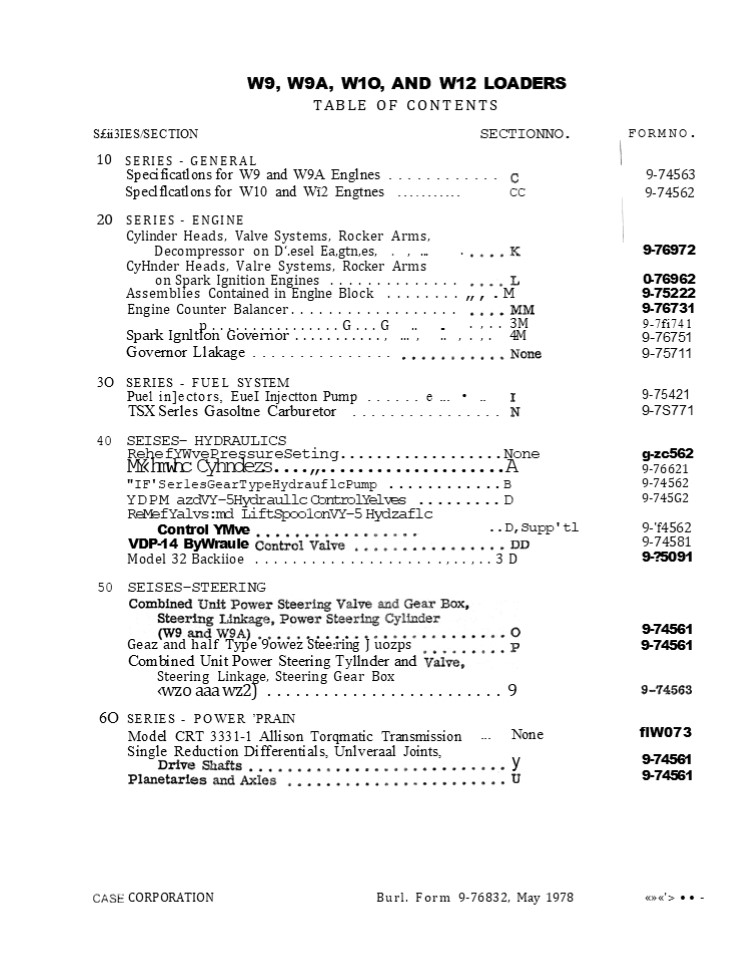
W9, W9A, W1O, AND W12 LOADERS TABLE OF
CONTENTS SECTIONNO.
Sii3IES/SECTION
FORMNO.
10 SERIES - GENERAL
Specificatlons for W9 and W9A Englnes ............ 9-74563
20 Speclflcatlons for W10 and Wï2 Engtnes ........... SERIES - ENGINE CC 9-74562
Cylinder Heads, Valve Systems, Rocker
Arms, Decompressor on D.esel Ea,gtn,es, . , ...
.
9-76972 0-76962 9-75222 9-76731 9-7fi741 9-76751 9
-75711
CyHnder Heads, Valre Systems, Rocker Arms
on Spark Ignition Engines ..............
Assemblies Contained in Englne Block ........
,.M Engine Counter Balancer .................. .
, . . 3M
p................G...G .. ...
Spark Ignltlon Governor ..........., ... , .. , .
, . 4M Governor Llakage ...............
3O SERIES - FUEL SYSTEM
Puel inectors, EueI Injectton Pump ...... e
... ..
9-75421 9-7S771
TSX Serles Gasoltne Carburetor ................
40 SEISES- HYDRAULICS
RehefYWvePressureSeting..................None
g-zc562 9-76621 9-74562 9-745G2
MYhmwhc Cyhndezs........................
A "IF'Ser1esGearTypeHydrauflcPump
............B YDPM azdVY-5Hydraullc ControlYelves
......... D
ReMefYalvsmd LiftSpoo1onVY-5 Hydzaflc
..D,Supp'tl
Control YMve
9-'f4562 9-74581 9-?5091
VDP-14 ByWraule
Model 32 Backiioe ................... .,..,..3D
50 SEISES-STEERING
9-74561 9-74561
Geaz and half Type 9owez Steering J
uozps Combined Unit Power Steering Tyllnder and
Steering Linkage, Steering Gear Box
wzo aaa wz2) ......................... 9
6O SERIES - POWER PRAIN Model CRT 3331-1 Allison
Torqmatic Transmission Single Reduction
Differentials, Unlveraal Joints,
... None y
flW073 9-74561 9-74561
Burl. Form 9-76832, May 1978
'gt -
CORPORATION
2
FORIANO.
SECTION NO.
SERIES/SECTION
70 SERIES BRAKES Sertes ''01" Hydraulic Brake
Cylinder,
Brake Shoes and Drums (W9, W9A) ............
9-74562
Power Assist Hydraulic Brake Valve, Brake Shoes
anti Drums (W10 . WW
9-74562 9-74563
Hydi ie Brake System ...,.... ..............
3W 80 SERIES - ELE CTRICAL
W9 Gasoline . .. . . . . . . . . . . None
9-76701 9-76711 9-76691 9-75202 9-76721
W9A Gasoline Electrical Systems
. None . None
W10, W12 Diesel Electrical 5ystems . . . . .
.. ...
Electrical System, Cranking Circuit,
Charging Clrcutt (24-volt Alternator) ..........
P
trlcal System . 3F
3
SERVICING THE
CYLINDER HEADS
SECTION
VALVE SYSTEMS ROCKER ARMS DECOMPRESSOR 3N CASE
POWRCEL DIESEL ENGINES
Rae . For m 9-7697 2
4
https//www.ebooklibonline.com Hello dear
friend! Thank you very much for reading. Enter
the link into your browser. The full manual is
available for immediate download. https//www.ebo
oklibonline.com
5
TABLFE O GORiTEi4TH CYL IND ER HEAD AND
COMPONENTS - Disassembly and Installation
. K-2 thrl K-
K-6
DE COMPRESSOR (If So Equipped) - Disassembly and
Assembly ........ , ..
ROCKER ARMS AND SHAFTS - Disassembly, Inspection
and Assembly ... , , , K-8
, . , K-10 . K10
CYLINDER HEAD AND VALVES - Disassembly and
Assembly ..... , ..
EXHAUST VALVE RO TATORS ......
VALVES, GUIDES AND SPRINGS - Inspection . . . .
. . . . . . . .. . . . . . . . . . K-12 INTAKE
AND EXHAUST VALVES - Ref acing . . . . . . . . .
. . . . . . .. . . . . . . K14 INTAKE AND
EXHAUST VALVE SEATS - Grinding ,
................. K-15 LOCATING TOP DEAD CENTER
AND TAPPE T ADJUSTMENT .... , .....
K-16 CVL.INDER HEAD AhtD COMFONENTS fReter Figur
e K-13 RemcsvaI
Steam clean the engine completely before doing
any dis assembly or service work, Drain cooling
system. Remove the intake, exhaust and water
manifolds. Remove the rocker arm covers.
Disconnect and remove the decompressor if so
equipped, Page K6. Remove the rocker arm
assemblies and tag them for proper installation.
(Refer to Page K-8. Disconnect the high pressure
fuel lines to
the injectors and cap them. Disconnect the fuel
leak-off tubes between each cylinder head and
cap them. Remove the push rods and tag or store
them in a holder or rack so they can be in-
stalled in their s ame locations.
Remove the cylinder he ad bolts or nuts and
lift the heads off the engine. Remove the head
gaskets and discard them.
Inspecticzn ancJ Installation
must be checked to determine which fire ring to
install. Only the standard fire ring is in-
cluded in the valve grind gasket kit, how-
ever a thicker fire ring (.004) is available if
the protrusion checks indic ate a need for it.
The thicker fire ring can be identified by a blue
marking stripe, Refer to Pages K4 and K5 for
the pro- cedure to follow when installing the
fire ring cylinder head gasket.
Remove all c arbon and cle an all parts before
installation. STANDARD HEAD GASKETS If you are
installing the standard gasket, install the new
gasket with new rubber seals , The gasket must be
installed with either the copper side up or the
side with the case part number up. Continued on
Page K-5. FIRE RING HEAD GASKETS If you are
installing the fire ring head gasket, inset B,
cylinder sleeve protrusion
K-2
6
HEAD
REMOVAL AND IhJSTALLATION OP C'V6INDER
AND COMP'ONENTS
DO NOT OVER TIGHTEN COVER NUT
DECOM PRES SO R
COV E R
COVER GA SK ET
I n s e t A
- ASKETS
GASK ET S o a
ROCKER A RM A S SEM BLY
o
FER RULE S
M A NI MOL DS EX H A UST
i NTA KE
WATE R M A N I FOL
A 5K ET S
HEA D BOLT
PUS H ROD
INTAKE F ER RUL E
M A NI FOL DS
ON E PIECE I NTAKE- EX HAUST MANI FOL D GASKET
E X H A U ST KE
I n s et B FI RE R I NG H E A D GA S K ET F I R
E RIN G GAS KET
CYLINDER HEA D
RUBBER SEAL S
GAS K ET
7
InspectIczn ance Installation lre Ring Qaaketa
CCczntinuecl7
The following procedure must be followed when
installing the fire ring head gasket
3. Using plate OTC970-12 from cylinder sleeve
puller OTC970, 010974AB ball and clamping
bar, clamp the cylinder sleeve in place,
Figure K-2. Torque the hold down capscrews
evenly to 50 foot pounds. JQ/J Refer to Figure
K-2 for clamping bar dimensions. These tools
are available through local Owatonna Tool Dealers
or the Owatonna Tool Co., Owatonna, Minnesota.
1. Clean the top surface of the block and
sleeve flange carefully. All traces of car- bon
and other deposits must be removed. During the
final cle arming operation, the use of a rag
dampened in solvent is re- commended. 2, Using a
small stone, remove any small burrs in the
areas to be measured so that accurate readings
can be obtained.
010 9 74AB B A L I OT C 970 - 12 P LAT E
M E A SURE SLEE VE PR OTRUSION
AT POINT S A ,B , C , A ND D . FQure K-2
Figure K-4. Regular line-up studs could be used
for most engines. In some in stances it is
very difficult to install the FIR F R I NG CROS
S S E CT ION
4. Either a magnetic base dial indicator or a
depth micrometer can now be used to determine the
cylinder sleeve protrusion as indicated in Figure
K3. Refer to chart, Figure K-5, to make sure the
correct fire ring is used.
g t LI P DOWN
A 4095 2 TONG
GA S K I T - PA RT N UM B ER U P
D I A L I ND ICAT 0 8
5LE V E
C Y LI N DE R SL 0 EV 5 PR OT R U SI 0 N
N 0 "O" RIN GS R E OUIR E D W IT H FI e E R IN G
GA 5 K ET
Figure K-3
A 4095 3 DOW E L
5. Install cylinder head gaskets.J _at_Q/QJ/ Two
of the capscrew holes in the gasket are slightly
smaller and act as guides to position the gasket
as well as the fire ring,
rear cylinder head due to the limited space
in which to place the head when lowering it down
over the long guide studs,
K-4
8
Inepecticzn ance InstallaticznCContinuecl)
CYLINDER SLEEVE PROTRUSION USE STANDARD FIRE RING USE STANDARD FIRE RING USE OVERSIZE(THICKNESS FIRE RING
BOTH SLEEVES UNDER ONE HEAD FLUSH TO .002
BOTH SLEEVES UNDER ONE HEAD .00 2 OR OVER BUT LESS THAN .0025 BETWEEN SLEEVES
BOTH SLEEVES UNDER ONE HEAD OVER .0025" DIFFERENCE BE TWE EN SLEEVES ON THE HIGH SLE EVE ON THE HIGH SLE EVE ON THE LOW SLEEVE
Figure K5
6. For difficult installations, the use of dowel
comprem sor (if so equipped.) Reter to Page
K-16 for propger firing order,
pins and a tong are recommended and can be
purchased through a local Snap-On Tool Dealer or
J.I. Case Central Parts Dept. under the following
part numbers.
Snap-On Tool No.
Case Part No. A40952 A40953
CF 83- l Tong CF 83-4 Dowel
7. Install the fire rings with the lip down-
wards , Figure K4. JQ/J Fire ring gas- kets must
be installed dry.
TI GH TEN I NG SEOU ENCE FigureK-6 13. Install
the rocker arm assemblies in their original
location.
8. Carefully clean the cylinder heads as des -
cribed in No. 1. If evidence of fretting or
erosion exist in the area of the fire ring
contact or if the head is warped more than
.005, the head must be resurfaced,
9. Install cylinder he ads and several bolts ,
then remove the A40953 dowels using A40952
tong and install all the bolts . STANDARD AND
FIRE RING HEAD GASKETS 10, Install intake and
exhaust manifold fer- rules and new gaskets . JQ
IQ When the manifolds are designed for the one
piece manifold gasket, the ferrules are used
only in the intake ports. Refer to Page K-3,
inset A. Install the intake and ex- haust
manifolds and torque to proper torque. Refer
to Specification Section, 11. Torque cylinder
head bolts or nuts to the proper sequence
illustrated in Figure K-6. The three torquing
steps recomm- ended are 50 foot pounds , 100 foot
pounds and finally 150 foot pounds.
- Adjust the valve tappet clearance, refer to Page
K- 16. - Bill cooling system and start engine. Check that
the rocker arms are receiving lubrication. - Run engine for approximately one (l) hour,
under load if possible,to thorough - ly warm up
the engine and se at the head gaskets . - l7. Stop the engine and retorque the cylinder
head bolts or nuts to 150 foot pounds while
the engine is still hot. Check and readjust the
tappets .
18. Cle an the rocker arm covers and re move
the old gasket. Install new gaskets and seals
then install covers . Refer to Specification
Section for proper torque. Do not over torque
the valve cover nuts.
12. Install the push rods in their original lo- c
ation. Connect the high pressure fuel lines
and leak-off , tubes Install the de-
K-5
9
INSP'ECTION OF DECOMP'RESSOR
CIf to CRefer
Ecjuippecl) Pigure K-T3
When the decompressor is engaged all the
exhaust valves must be held in an open position.
Inspect the trip pins for excessive wear. Inspe
ct for bent or worn control linkage if the valves
are not held open. When the decompressor is
disengaged and the tappet clearance is correct be
sure the trip pins release the rocker arms
completely. Inspect for loose coupling set
screws, bent or worn control linkage, control
link cotter pin missing or a pin in one of the
control levers sheared off. DIEASSEM_at_LV OP
DECOMFRESSOR fRefer ten Figure K-T3
levers (8) . Remove the control shafts (9)
from the housings. Remove the control lev- ers
(8) . Remove the trip pins (10) from the
decompressor shaft (11) . Remove and dis- card
the "O" rings (12) from the shafts.
Remove the control links cotter pins (1) and
link (2) . Remove the decompressor control
housings (3) and the housing gaskets (4) .
Loosen the coupling set screws (5) and re- move
the coupling (6) . Remove the roll pins (7) from
the control
AESEM6V CRefer Figure K-V3
ing (6) and tighten square head set
screws (s). Install the housing and shaft
assembly to the cylinder heads with new gaskets
(4) . In- stall the control link (2) with cotter
pins (1) .
Install the trip pins (10) and lever (8) with
roll pin (7) to the decompressor mounting
brackets (13) . Install the new "O" rings (12) on
the shafts - Install the shafts (9) into the
housings (3) and install the control levers (8)
with roll pins (7) . Install the shaft coupl-
DECOMP'RESSOR ADJUSTMENTS CRefer to Figure
K-TJ The stop bolts (14) in the coupling stop (6)
should be adjusted so the decompressor can open
the valves when engaged and lift the trip pins so
they are clear of the rocker arms when dis-
engaged (Refer to Inset A) . Tighten the lock
nuts (15) on the stop bolts (14) after adjustment
is made.
K-6
10
(No Transcript)
11
DIGAEEEIUIL.Y OF ETH ROCKER ARIVIG
CRefer Hemove the rocker arm shaft bracket
studs (15) and bolts (16) . Remove and tag shaft
a- ssemblies for installation.
Figure K-BJ
using a rod and driving one plug clear thru the
shaft. This will also clean out the dirt or
sludge that has formed inside of the
shaft, Replacement shafts have these plugs in-
stalled at the factory. Remove the push rods and
store them in a rack or holder so they can be
installed in their original loc ation, Remove
the oil wick (11) from each ex- haust rocker
arm and discard. Remove the bushing (12) from the
cast rocker arm if it is worn using an Arbor
(See Inset A).
Unscrew the oil tube (1) and discardthe "O" ring
(2). Remove the snap rings (3), spacer washer (5)
and keep count of the number of washers at each
end of the shaft. Tag each rocker arm for
original location. Remove the exhaust rocker arms
(6) and the shaft brackets (7) from e ach end of
the shaft.
Remove the intake rocker arms (8) and the shaft
spring (9) . Remove the plugs (10) by
iuswecziou CRefer to Figure K-_at_3
Inspect the shaft spring for proper tension and
J0roken coils, Refer to "Specification" Section.
Inspect the rocker arm shaft for ex- cessive worn
spots on the bottom side of the shaft. Replace
shaft if worn condition exists. Inspect the
rocker arm bushings by in- stalling each rocker
arm on the shaft in its proper location. The
rocker arm must be free on the shaft without any
side "wobble"
bushing or replace the stamped rocker arm, Note
the stamped rocker arm Bushing is not
replaceable. Replacement rocker arms come
complete with bushings . Inst ect the valve
contact area on the rocker arm for wear. Replace
if worn. Inspect the tappet adjust- ing screw for
we ar marks or pitting. In- spect the push rods
for straightness , crack- ed or worn ends .
If any is noted replace the cast rocker
arm AGGEM_at_LV CRefer to Figure K-_at_)
Clean all parts thoroughly. Pl ace new bushing
on Arbor and press into the cast rocker arm so
the bushing (12) is evenly centered in the
rocker arm and the oil hole is lined up with the
oil hole in the rocker arm, (See Inset A) .
Check the bushing for high or rough spots and
if they exist, they should be honed out. Install
new oii wick (11) in the exhaust rocker arm.
Lubricate each part with engine oil as they are
installed. Install a shaft spring (9) and two
intake rocker arms (8) on the shaft (4) , When
in- stalling the cast rocker arms the adjusting
screw and the shaft oil hole must be on the s
ame side, (See Inset A) .
(6) on the shaft. Install the same number of
spacer washers (5) that were removed.
Install the snap rings (3) at each end of the
shaft. Check the rocker arms for free move -
ment. Install the oil tube (1) with new "O" rin,
g (2) Install the push rods in their ori- ginal
location if they were removed. Install the
adjusting screws (l3) and lock nuts (14) if they
were removed. Install the rocker arm and shaft
assembly on the cylinder head. Make sure all the
push rods are engaged with the adjusting screws.
Install the bracket studs (15) and bol,ts (16)
Refer to "Specific ation" Section for proper
torque, Check that the oil tube is in the oil
hole in the cylinder head. Check exhaust
rocker arms for excessive end play. One or more
spacer washers can be used between the rocker
arm and snap ring to remove the excessive end
play. Check and adjust the tappet cle arance,
(Refer to Page K 16.)
When installing the stamped steel rocker arms the
adjusting screw and the shaft oil hole must be on
opposite sides (See inset B) .
Install the shaft brackets (7) on the shaft with
the split side toward the push rod side of the
engine, Install the exhaust rocker arms
K-8
12
BU S HING OIL HOL E
INSET A
BUS H I NG OIL HOLE
IFJSET B
S H A FT OIL HOL
SHA F T OIL HOLE
OI L W ICK BUS HING CA ST I RON EXHA U 5 T
ROCKER A RM
STAMPED 5T EE L ROCKE R A R M
ROCKER A RM ASSEM BLY
Figure X-8
K-9
13
DISAGOEMBLV OF THE CV1INDER HEAD AND
VALVES CRefer to Figure K-O)
Using a valve spring compressor (Refer to
Inset A) compress the spring (1) . Remove the
valve retainer locks (2) and the spring retainers
(3) or valve rotators (4) . Remove the valve
springs (1) , valve stem oil seal (5) and the
valve spring seat. Remove any car- bon irom the
valve stems before they are moved from the
head. Remove the intake valves (7) and the ex
haust valves (8) from the head and store them in
a rack or holder. Remove the in- talse valve
guide (9) exhaust valve guide (10)
down through head using an Arbor (See Inset B) .
Refer to "Specification" Section for dim- ension
of valve guides. The exhaust valve seats (11)
can be removed with a special seat removing tool
(See Inset C) .
JQ Never attempt to remove a valve seat with a
center punch, cold chisel or pry bar.
Toremovethe expansonpug(12)itmust be dzflled
andthen pryed ou.
ASSEML.Y CRefer ten Figure K-p Clean head
completely and check for cracks . Remove all
carbon from the bore of the valve guides with a
wire brush and blow out with compressed air.
Install new valve guides (9 and 10) using an
Arbor (See Inset B) and press the guides into the
head from the top of the head. The distance the
guides must protrude above the head is given in
the "Specification" Section. To install new
exhaust valve seats (11) clean the recess in
the cylinder head. Place the valve seats in dry
ice to shrink them for easy installation.
Insert the valve seats in the head and drive
them in place using suit- able driver. Lubricate
the valves (7 and 8)
with engine oil and install them in the ori-
ginal location. Install the valve spring seats
(6) , valve springs (1) and intake valve stem
oil seal (5) . Install the exhaust valve rotators
(4) and the intake valve spring retainers (3) .
Com- press the valve springs so the valve retain-
er locks (2) can be installed.
Wstalnew expansionplug(12).Referto Page K-2 for
reinstalling the cylinderhead.
EXHAUST VALVE ROTATOR
CRefer When re-installing the rocker arm assem-
bly, check the operation of the exhaust valve
rotators. To check the operation of the ro-
tators, place a dab of white paint on the ro-
tator - note its position -- then start the
engine and observe whether or not the ro- tator
is turning. Replace any rotators that will not
turn. Do not attempt repairs on ro- tators. It is
impossible to determine whether or not the
rotator is turning without an identify- ing
mark. There is no set speed at which the rotators
should turn some rotators will turn faster than
others. As long as the rotator is turn- ing the
valve, it is functioning properly.
Figure tK-O
An excessive accumulation of deposits on the
exhaust valve face and stem is also an in-
dication that the rotators may not be function-
ing properly.
When installing valve rotators
Reassemble the rotator with original valve as
they tend to become matched parts when they wear
in. If it is necessary to install a new valve
al- ways install a new rotator and retaining lock.
K-10
14
DISAESEM6V AND ASSEML.Y OF THE CCL.IhI
DER HEAD AND VAL.VER
I N SET B VALVE GUI DE PRESS ING A RBOR I
INSET A
ROTATOR
I NSET C X H AU ST SEAT REMOV I NG
Figure K-5
Figure K-9
K-11
15
iuswecxion or" 3-ne vAuves,nuioes ono swRiuns
Valve springs should be checked for flat
squared ends, broken or cracked coils and
correct spring pressure. Use a Valve Spring
Tenslon Tester. Refer to the Specification
Section.
E X PA ND A BLE BORE GAUGE
Valve guides can be checked for wear by using a
bore gauge and micrometer ( Refer to Figure
K-11)The valve guide should be check- ed at the
top, middle and bottom of the bore for wear.Refer
to Fiptire 10. The inside dia- meter wear limits
of the valve guide should not exceed the
specification given. in the Spec- ification
Section, at any point along the bore of the
guide. Replace guide if it does. Check the new
valve guides after installation to make sure that
the bore is not less than the inside diameter
given .n the Specification Section. Using an
Arbor equal to the inside diameter of the valve
guide will keep the guide from collapsing when
pressed in place. Clean the valves with a power
driven fine wire brush, being very careful not to
scratch the valve stems. Reference is made to the
dif- ferent parts of the valve (Refer to Figure
K-12.) Inspect the valves for excessive wear
or necked stems (Refer to Figure K-13) . This can
be caused by lack of lubrication, plugged or
dirty water passages or operating the engine
under continuous overload at excessive engine
RPM. Valves should be replaced.
C H E C K W E A R OF V ALV E GUIDE AT
THREE _/ POINTS AT LEAST
Figure K-10
MICROM ET R
Figure K-11
RETA I N ER GROO VE
FACE
HE A D
ST EJU
MARG I N
Figure x-12
Inspect the valves for deep grooves in the face
(Refer to Figure K-14.) This can be cau- sed by
abrasives entering the engine through the intake
system or not servicing the air cleaner
regularly. A leaking valve cover gas- ket can
also cause this condition. If grinding the valve
face will not correct this condition, discard the
valves. Inspect the valve face and stem for rust
or pitting (Refer to Figure K-lñ). Rust or
pitting can usually be removed by grinding the
valve face. If rust or pitting on the valve stem
exist the valve should be replaced. These
conditions can be caused by using poor quality
engine oil or fuel that doesn't meet the
specification giv- en in the Operator's Manual.
Rust could be caused by improper storing o1 the
engine.
VALV E ST EM N ECKE D
I _
Figure K-13
GRO OV E IN VALV E FAC E
Figure K-14
RUST OR PITT I
Figure K-15
K-12
16
iuspec-rlor4 oj xwe va,uves,cuioes a,no
sprtincs Heavy carbon or varnish derCSits on
the
valve (Refer to Figure K- 16) should be re- moved
before valves are ground. This condi- tion is
usually caused by worn piston rings and sleeves
which allow too much oil to reach the combustion
chamber. This condition could also be caused by
worn valve guides or no seals on the intake
valves. Low operating temperature is still
another cause. These conditions should be
corrected or the same trouble with the valves
will happen again. Inspect the valve head for
dishing and the valve face for deep burned
spots, Figure K- 17. These conditions can't be
corrected by grinding the valves. The valves
should be re- placed. These conditions are
usually caused by running the engine under
excessive load at high engine temperatures. Valves
with worn keeper grooves or the stem is
worn or dished beyond the chamber must be
replaced (Refer to Figure K- i8) .
HEAVY C A R BON A ND VA RN I S H DE POSI T S
Figure K-16
/ DEE P BU R N ED VALV E FACE
DI S H E D VALV E HE A D
Four WO R N R ETA I N ER GROO VE
WOR N STEM TI P Figure K-18
M ICROM ET E R
The checking of the valve stem diameter can best
be done with a good accurate mi- crometer (Refer
to Figure K-19) . The valve stem should not
vary more than the wear limits given in the
"Specification Section at any point on the valve
stem. If this condition exists the valves must be
replaced. The checking of the valve face runout
should be done after the valves have been ground.
A Vee block type holder with a dial indicator
(Refer to Figure K-20) should be used to check
the valve face runout. The valve face should not
vary more than the specification given in the
"Specification Section. The valve stem runout
can also be checked with this Vee block and dial
indicator.
CH ECK DI AM ETER OF STEM AT T H REE POINTS AT
LEA ST
Figure K-19
C H ECK I NG VALV E FACE R U NOU T
DI AL I ND ICATOR
Small amounts of very fine pitting, Figure K-21,
may be found on the surfaces of the valve faces
and seats after the valves are cleaned. These
are normal and will not affect engine
performance. This fine pitting is cau- sed by a
normal oxidation process and can happen on any
engine during the run-in per- iod. It is not
necessary to grind valves or seats if this fine
pitting is found as the pit- ting will generally
reoccur after the engine is run for a few hours.
Figure K-20
FI N E PIT TI NG
Figure K-21
K-13
17
REFACING INTAKE AND exwAusx vAuves Before
refacing the valves they should be
wire brushed, cleaned and inspected. Refer to the
Specification Section for the correct valve
face grinding angle. Set the refacing machine
protractor at this angle. Be sure the chuck of
the machine is clean before installing valve.
Dress the grinding wheel before start- ing to
reface each valve. Take only light cuts as the
valve is refaced and the last cut must be very
fine so the valve face will have a pol-
ishedfinish.
t
VALV E FAC E G RI ND I NG A NGL E
M A RGI N
J _at_Q/_at_J/ Replace any valve that after grinding
has a thin edge or margin (Refer to Figure K-22)
. If the margin on the ground valve is less than
half the margin on a new valve replace the valve .
C H AJ\/\ FER
"
The tip end of the valve should be checked for
roughness or wear. Usually this can be re- moved
with some very light cuts against the side of the
grinding wheel and will square up the end. Never
grind the chamber off the valve stem end. Any
excessive grinding should not be done to the stem
end. Replace the valve. Before installing new
valves a fine finish grinding should be done to
each new valve. Check the valve face and valve
stem runout before installing (Refer to Page 13)
. The valve face and seat contact location
should be checked. Place valve bluing (Prus- sion
Blue) on the face of the valve. Install the valve
ln the head and rotate the valve on its seat.
Remove the valve and inspect the contact area on
the valve face. The bluing will have been removed
from the valve face evenly at the top edge of the
contact area (Refer to Fig- ure K-23) . This is
due to the fact that the valve face and seat are
ground with 1 INTER- FERENCE ANGLE. Refer to
Specification Section. When the top edge of the
contact area is too high or low on the valve
face, the seat contact area must be moved. This
is done by using the narrowing stones (Refer to
Page K-15). The contact area width should never
exceed the dimension given in the Specification
Section.
Figure K-22
COR REC T CONTACT LOCATION
I NCOR R ECT CON TAC T LOCATION
BLGU I N
CON TAC T A RE A W I D T H
Figure K- 23
tff/4J DO NOT USE BLUING TO CHECK VALVE SEAT AND
VALVE FACE RUN-OUT. The valve face could be
contacting the seat at only a few points, but the
bluing would still be rubbed off by the high
points and make it appear as though you had solid
contact all around. The only thing bluing will
indicate is the location on the valve face where
the seat is contacting -- no more! K-14
18
GRIN OING INTAKE ANO EXHAUST VALVE SEATS
Always use a precision type power seat grinder
similar to the one shown in Figure K- 24. The
valve seats can not be ground with manual
operated equipment. The intake valve seat is part
of the head and for this reason only a finishing
stone should be used to grind the seat. The
exhaust valve seat should be first ground with a
roughing stone and then use a finishing stone.
Take very light cuts with the grinding stones so
just enough metal is removed to end up with a
good smooth seat finish.
POW ER SE AT GRI NDE R
Figure K-24 VA LV E SE AT G R.I N D IN G A NGL E
Refer to the Specification Section for the
proper specifications of the intake, exhaust
seats and valve guides (Refer to Figure K- 25)
.From the specifications the proper grind- ing
stones and pilot can be chosen. When using the
grinding stones the seat grinding angle of the
stone should be dres- sed on a (stone dresser)
frequently so the seat angle will not vary when
grinding the seats.
sBEP
INTAK E VALVE SEAT
EX H A U ST VA LV E SEAT I N SE R T Figure K -25
The valve seat runout should be checked after
finish grinding with a dial indicator and seat
grinding pilot (Refer to Figure K- 26) . After
checking the runout, turn the pilot 1/4 turn and
check runout again. The width of the valve seat
contact area must also be checked. Refer to
Specification Section for dimension of seat
width contact area. The valve seat contact area
width should never vary from this dimension.The
exhaust valve seat contact area width and
location can be changed by using the 30 and 60
iar- rowing stone Refer to Figure K-2 7.
DI AL I N DI CAT OR
Figure K-26
QJ The intake valve seat should not be changed
by using the narrowing stones. lf the seat width
exceeds the dimension given in the
"Specification Section, the cylinder head should
be replaced. When the step above the intake seat
(Refer to Figure K- 25) has been reduced by the
grinding operation, installing a new valve
will help to restore the compression that would
normally be lost by excessive grind- ing of the
seat and valves. Excessive grind- ing of the
valves and seats moves the valves further into
the head thereby reducing the compression ratio.
N A R ROW I N G STON E
SE AT W I D l T H
N A R ROW I NG STON E Figure J-27
K-15
19
L-OGAGTli"d TOP OHAO GENTHU AMO TABLET AONUHTM
Ef'4T Refer to Specification Section for the
correct tappet cle arance . The two valve
tappets for each cylinder are to be checked and
ad jus ted when the piston for that particular
cylinder is at top de ad center on the
compression stroke . Start with the number 1
cylinder (nearestr the adiator) and follow the
sequence of firing order. A Oylincier
firing Qrder -------------
------------ -1-3-4-2 cylinder No. 2 can be
rocked open or closed slightly by crank movement.
Adjust tappets on No. 3 Cylinder.
The top de ad center position of the pistons for
checking valve clearance is indicated by marks on
the crankshaft pulley flange. The 4 cylinder
engines use the marks 180 apart, Figure K-28.
ADJU STING
SCRE W
LOCK N U T
g
TDC
MARK FOR CA ECKING VALVE CLEARA0NCE CYLINDERS 1
AND 4
CRANKSHAFT PULLEY
E X H A U ST
I NTA K E
E X H A U ST
E X HAU 5 T
O
DOUBLE MARK FOR CHECKING VALVE CLEARANCE ON
CYLINDERS 2 A ND 3
Figure K29
NUMBER 4 CYLINDER Crank engine another 1/2
revolution or until the push rods on No. 4
cylinder are loose and the rocker arms on No. 1
can be rocked open or closed slightly by
crank movement, Adjust tappets on No. 4 cylinder.
F'igure K28
NUMBER 1 CYLINDER To set No, 1 cylinder on top of
compres - sion stroke remove the valve
covers and crank engine until the push rods
are loose on No, 1 cylinder (top of compres sion
stroke) and the rocker arms on the opposing cyl-
inder No. 4 can be rocked open orclosed with a
slight back and forth movement of the crankshaft,
Then check and adjust the valve tappets on No, 1
cylinder, refer to Figure K- 29.
NUMBER 2 CYLINDER Crank engine another 1/2
revolution or un- til the push rods on No. 2
cylinder are loose and the rocker arms on No. 3
can be rocked open or closed slightly by crank
movement. Adjust tappets on No. 2 cylinder. While
the valve covers are removed, start the engine
and check that the rocker arm assemblies are
receiving proper lubrica- tion then install new
valve cover gaskets and repl ace valve covers
properly to pre- vent oil leaks .
NUMBER 3 CYLINDER Crank the engine approximately
1/2 turn or until the push rods on No. 3
cylinder are loose and the rocker arms on the
opposing
K16
20
L.OCATING TOP DEAD-OENTER Aht TAFFET
ADJUSTMENT D Cylincler Fiing Order 1-5-3-6-2-
NUMBER 5 CYLINDER Crank the engine approximately
1/3 turn or until the push rods on No. 5 are
loose and the rocker arms on No. 2 can be
mocked open or closed slightly by crank movement.
Adjust tappets on No. 5 cylinder. NUMBER 3
CTLINDER Crank engine another 1/3 revolution or
until the push rods on No. 3 cylinder are loose
and the rocker arms on No. 4 can be rocked open
or closed slightly by crank movement. Adjust
tappets on No. 3 cylinder. NUMBER 6
CYLINDER Crank engine another 1/3 (TDC mark)
revolution or until the push rods on No. 6 are
loose and the rocker arms on No. 1 can be
rocked open or closed slightly by crank
movement. Adjust tappets on No. 6
cylinder. NUMBER 2 CYLINDER Crank engine another
1/3 revolution or until the push rods on No.
2 cylinder are loose and the rocker arms on No. 5
can be rocked open or closed slightly by
crank movement. Adjust the tappets on No. 2
cylinder. NUMBER 4 CYLINDER Crank engine anothe r
1/3 revolution or un- til the push rods on No. 4
cylinder are loose and the rocker arms on No 3
can tae rocket open or closed slightly by crank
movement. Adjust the tappets on No. 4 cylinder.
The top dead center position of Nos. 1 and 6
cylinders is indic ated by the TD C mark on the
cr anlsshaft pulley flange.
MARK FOR CHECKING
TDC
VALVE CtEAR ANCE ON CYLINDERS NOS. 1 AN D 6
CRANKSHA FT
MARK FOR CH ECKING VA LVE CLEA RA NCE ON CYLIN
DRS NOS. 2 A N D S
MAR K FOR CHECKING
VALVE CLEARANCE
ON CYLINDERS NOS.
AND 4
Figure K-30 NUMBER 1 CYLINDER To set No. 1 cyl
inder on top of compres - sion stroke, remove
the valve covers and crank engine until the
push rods are loose on No. 1 cylinder (top
of compression stroke) and the rocker arms on
the oppos - ing cylinder No. 6 can be rocked
open or closed with a slight movement of the
crank- shaft. Then crank and adjust the
valve tappets on No. 1 cylinder, refer to Figure
ii-31. A DJ U STI G SC R E W
E X H A U ST
E X H A U ST
x/
E X H A U ST
E X H AU 5 T
Figure K-31
K- 17
21
SERVICINTGHE
SECTION
- CYLINDERHEADS
- VALVE SYSTEMS ROCKER ARMS
- ON
- CASE POWRDYNE SPARK IGNITION ENGINES
R oc .F or m 9 - 76962
22
C YLIND ER HEAD AND COMPONENTS - Disassembly and
Install atioil . L- 2 thru L-5 ROC KER ARMS AND
SHAFTS - Disassembly, Inspection and Assembly ,
..... L-6 C YLIND ER HEAD AND VALVES -
Disassembly and Assembly ............ L-8 EXHAUST
VALVE ROTATORS ....................... ..........
LB VALVES, GUIDES AND SPRINGS - Insp ection
...................... L-10 INTAKE AND EXHAUST
VALVES - Ref acing . ...................
.L-lz INTAKE AND EXHAUST VALVE SEATS - Grinding
.................. L-13
LOCATING TOP DEAD C ENTER AND TAP PET
ADJUSTMENT , .. , .. , ... CYLINDER HEAD AND
COMP'ON ENTS Refer ten Pisure k-1) Removal
L14
Steam cle an the engine completely before doing
any dis assembly or service work.
tag them for proper installation. (Refer to Page
L -6) . Remove the push rods and tag or store
them in a holder or rack so they can be in-
stalled in their s ame locations .
Drain cooling system. Disconnect the fuel line,
throttle and choke control at the c arb- uretor.
Remove the spark plug wires from each spark
plug. Remove the intake, exhaus I and water
manifolds. Remove the rocker arm covers .
Remove the cylinder he ad bolts or nuts and
lift the heads off the engine . Remove the he ad
gaskets and dis card them.
Remove the rocker arm assemblies and Inspect
icon ancl Installation
must be checked to determine which fire ring to
install. Only the standard fire ring is in
cluded in the valve grind gasket kit, hour-
ever a thicker fire ring (.004) is available if
the protrusion checks indicate a need for it.
The thicker fire ring can be identified by a blue
marking stripe. Refer to Pages L-4 and L -5 for
the pro- cedure to follow when installing the
fire ring cylinder head gasket.
Remove all carbon and clean all parts before
installation, STANDARD HEAD GASKETS If you are
installing the standard gasket, install the new
gasket with new rubber seals . The gasket must be
installed with either the copper side up or the
side with the case part number up. Continued on
Page L-5, FIRE RING HEAD GASKETS If you are
installing the fire ring head gasket, inset B,
cylinder sleeve protrusion
L-2
23
REMOVAL.
ANED
lNSTALLATION OF OV1INDER HEAD
nuo couioneu"rs
DO NOT OV ER TIGHTEN COV ER NU TS
I N S ET A WATER . , M A NI FOL D
C OV E R
G A SKE T S
GA SK E T S
COV ER G A SK ET
F R RULE S
M A NI FOL D S rx Hqusr
q
NTA K E
ROCK E k A RM A SS EM BLY
WAT E R M A NI FOL D "" e
,
M A NI FOL D S
INTAKE F ER R ULE
ON E PI EC E I N TAK E- E X H AU ST M A NI FOL D
GA SKET
H A U ST
INTKE
HEA D BOLT
PU S H ROD
I NS ET B FIR E RI NG HE A D GA 5 K ET F IR E
R I N G GASK ET
CYL I NDE R HEA D
R UBBER SEAL S STAN DAR G A S K ET FureL-1
L-3
24
Inspection ance Installation Pire Ring
GasketsCContinueclJ
The following procedure must be followed when
installing the fire ring head gasket
3. Using plate OTC 970-12 from cylinder sleeve
puller OTC 9i0, 010974AB ball and ol amping
bar, clamp the cylinder sleeve in place,
Figure L-2. Torque the hold down capscrews
evenly to 50 foot pounds . JQ /J Refer to
Figure L2 for clamping bar dimensions .
1. Clean the top surface of the block and
sleeve fl ange carefully. All traces oJ car bon
and other deposits must tae removed. During the
final cleaning operation, the use of a rag
dampened in solvent is re commended.
These tools are available through local
Owatonna Tool Dealers or the Owatonna Tool
Co., Owatonna, Minnesota.
2. Using a small stone, remove any small faurrs
in the areas to be me asured so that accurate re
adings can be obtained.
CL A M P I N G B A R 0 10 9 74 A B B A L L OT C
9 70 - 12 P L AT E
M E A SU R E S L E E V E P R OT R USION AT POINT
S A ,B , C , A N D D . FigureL-2
4. Either a magnetic base dial indicator or a
depth micrometer can now be used to determine
the cylinder sleeve protrusion as indicated in
Figure L-3, Refer to chart, 1'igure L-5, to make
sure the correct fire ring is used.
Figure L4. Regular line-up studs could be used
for most engines . In some in- stances it is
very difficult to install the F I R E R I NG CR 0
S S S E C TI ON A40952 TONG fi t LI P D OWk GA
S K ET - PA RT N U M B E R U P
D I A L I N D IC AT O R
C YLIND E R S L E E V E
C Y LI N D E R S L E E V E 0 PR OT RU SIO N
N 0 RI N GS R EOU I RE D W IT H FIRE RI N G
GA S K ETS
Figure L-3
A 409S 3 DOW E L
F1gure k-4
5, Install cylinder head gaskets. I p (
rear cylinder head due to the limited space
in which to place the head when lowering it down
over the long guide studs.
Two of the capscrew holes in the gasket
are slightly smaller and act as guides to
position the gasket as well as the fire ring,
L-4
25
Inspecticzn ance
CYLINDER SLEEVE PROTRUSION USE STANDARD FIRE RING USE OVERSIZE(THICKNESS FIRE RING
BOTHSLEEVESUNDER ONEHEAD FLUSH TO.002"
BOTH SLEEVES UNDER ONE HEAD .0 02 OR OVER BUT LESS THAN .0025 B ETWEEN SLE EVES
BOTH SLEEVES UNDER ONE HEAD OVER .00 25 DIFFERENCE BETWEEN SLEEVES ON THE HIGH SLE E VE ON THE LOW SLE E VE
Figure L5
6. For difficult installations , the use of dowel
sparkpugwires, RefeitoPageL-l4for proper firing
order.
pins and a tong are recommended and can be
purchased through a local Snap-On Tool Dealer or
J.I. Case Central Parts Dept. under the following
part numbers,
Snap-On Tool No. Case Part No.
CF83- l Tong CF83-4 Dowel
A40952 A40953
- Install the fire rings with the lip down- wards ,
Figure 4. (fl Fire ring gaskets must be
installed dry. - Carefully cle an the cylinder heads as des-
cribed in No. 1. If evidence of fretting or
erosion exist in the area of the fire ring
contact or if the head is warped more than
.005, the head must be resurfaced. - Install cylinder he ads and several bolts ,
then remove the A40953 dowels using A40952
tong and ins tall all the bolts. - STANDARD AND FIRE RING HEAD GASKETS
- Install intake and exhaust manifold fer- rules
and new gaskets . JQ /J When the manifolds are
designed for the one piece manifold gasket, the
ferrules are used only in the intake ports .
Refer to Page L3, inset A, Install the intake
and ex- haust manifolds and torque to proper
torque. Refer to Specification Section. - Torque cylinder head bolts or nuts to the
proper sequence illustrated in Fig- ure L-6.
The three torquing steps re- commended are 50
foot pounds , 100 foot pounds and finally 150
foot pounds.
.
TI G H T E N l f'IG 5 EOU E NCE
Figure L 6
Install the rocker arm assemblies in their
original location.
14. Adjust the valve tappet clearance, refer to
Page L -14. is. Fill cooling system and start
engine . Check that the rocker arms are receiving
lubric ation, 16. Run engine for approximately
one (1) hour, under load if possible , to
thorough- ly warm up the engine and se at the
head gaskets .
IT.
Stop the engine and retorque the cylinder head
bolts or nuts to 150 foot pounds while the
engine is still hot. Check and re adjust the
tappet,
18. Clean the rocker arm covers and re- move
the old gasket. Install new gaskets and seals
then install covers . Refer to Specification
Section for proper torque. Do not over torque the
valve cover nuts .
12. Install the push rods in their original lo-
cation, Heconnect the fuel line , throttle
control and choke control. Reconnect the
L5
26
Suggest If the above button click is invalid.
Please download this document first, and then
click the above link to download the complete
manual. Thank you so much for reading
27
Remove the rockier arm shaft laracket studs
(15) and bolts (16) . Remove and tag shaft
assemblies for installation. Uns crew the oil
tube (1) and disc ard the O ring (2) . Remove
the s nap rings (3) , spacer washer (5) and keep
count of the num ber of washers at each end of
the shaft. Tag each rocker arm for ori ginal
location. Re move the exhaust rocker arms (6)
and the shaft brackets (7) from each end oI the
shaft. Remove the intake rocker arms (8) and the
shaft spring (9). In rocker shafts not re amed
with stamped steel cup plugs, inset C, re move
the plugs (10) by using a rod and driv-
also clean out any sludge that has accumu- lated
inside of the shaft. To remove cup plugs (10) in
reamed rocker shafts , Inset "Cdrill hole thru
the plug and remove. Rocker shafts with aluminum
type plugs, Inset D are per manent type. The
plugs are not replaceable. Replacement shafts
have these plugs instal led at the
factory. Remove the push rods and store them in a
rack or holder so they can be installed in
their original location, Remove the oil wick(11)
from each exhaust rocker arm of the cast iron
type and discard Remove the Bushing (12) from the
cast rocker.
ing one plug clear thru the shaft. This will arm
if it is worn using on Arbor(See Inset A) .
Iwswec-non Refer to Figure L.-T3
Inspect the shaft spring for proper tension and
broken coils, Refer to Specification Section.
Inspect the rocker arm shaft for ex cessive worn
spots on the bottom side of the shaft. Replace
shaft if worn condition e, xists Inspect the
rocker arm bushings ley in- stalling each rocker
arm on the shaft in its proper location. The
rocker arm must be free on the shaft without any
side wobble".
In the cast rocker arms if any is noted, re
place the bushing. In the stamped rocker arms
the Bushing is not replaceable. Re placement
rocker arms are purchased com- plete with
bushings . Inspect the valve contact area on the
rocker arm for wear. Replace if worn. Inspect
the tappet adjusting screw for we ar marks or
pitting. Inspect the push rods for straightness ,
cracked or worn ends .
AGSEML.Y
Fig ure L.-V of the engine. Install the exhaust
rocker arms (6) on the shaft. Install the same
number of spacer washers (5) that were
removed. Install the snap rings (3) at each end
of the shaft. Check the rocker arms for free
move- ment. Install the oil tube (1) with new
O ring (2) . Install the push rods in their
origin- al location if they were removed. Install
the adjusting screws (13) and lock nuts (14) if
they were removed. Install the rocker arm and
shaft assembly on the cylinder head. Make sure
all the push rods are engaged with the adjusting
screws . Install the bracket studs (15) and
bol,ts (16) Torque studs and bolts 54 to 64 foot
pounds . Check that the oil tube is in the oil
hole in the cylinder head. Check exhaust rocker
arms for excessive end play. One or more spacer
washers (5) can be used between the rocker arm
(6) and snap ring (3) to remove the ex- cessive
end play. Check and adjust the tappet clearance.
(Refer to Page L-14) .
CRefer
Clean all parts thoroughly. Place new bushing
on Arbor and press into the cast rocker arm so
the bushing (12) is evenly centered in the
rocker arm and the oil hole is lined up with the
oil hole in the rocker arm, (See Inset A) .
Check the bushing for high or rough spots and
if they exist, they should be honed out. Install
new oil wick (11) in the c ast iron exhaust
rocker arm. Lubri cate each part with engine oil
as they are ins talled. Install a shaft spring
(9) and two intake rocker arms (8) on the shaft
(4) . When in- stalling the cast rocker arms,the
adjusting screw and the shaft oil hole must be
on the s ame side. (See Inset A) , When
installing the stamped steel rocker arms, the
adjusting screw and the shaft oil hole must be on
opposite sides (See inset B) . Install the shaft
brackets (7) on the shaft with the split side
toward the push rod side
L-6
28
https//www.ebooklibonline.com Hello dear
friend! Thank you very much for reading. Enter
the link into your browser. The full manual is
available for immediate download. https//www.ebo
oklibonline.com
Recommended
CrystalGraphics Presentations


