
CASE IH JX75 Tractor Service Repair Manual Instant Download
Title:
CASE IH JX75 Tractor Service Repair Manual Instant Download
Description:
CASE IH JX75 Tractor Service Repair Manual Instant Download –
Number of Views:0
Title: CASE IH JX75 Tractor Service Repair Manual Instant Download
1
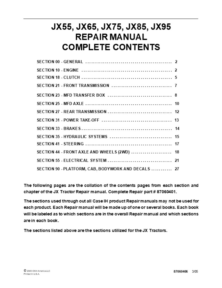
JX55, JX65, JX75, JX85, JX95 REPAIR MANUAL
COMPLETE CONTENTS
- SECTION 00 - GENERAL .............................
............... 2 - SECTION 10 - ENGINE ..............................
................ 2 - SECTION 18 - CLUTCH ..............................
................ 5 SECTION 21 - FRONT
TRANSMISSION ............................... 7 - SECTION 23 - MFD TRANSFER BOX ....................
............. 8 - SECTION 25 - MFD AXLE ............................
................ 10 - SECTION 27 - REAR TRANSMISSION ...................
.............. 12 - SECTION 31 - POWER TAKE-OFF ......................
.............. 13 - SECTION 33 - BRAKES ..............................
................ 14 - SECTION 35 - HYDRAULIC SYSTEMS ...................
............. 15 - SECTION 41 - STEERING ............................
................ 17 SECTION 44 - FRONT AXLE AND
WHEELS (2WD) ..................... 18 - SECTION 55 - ELECTRICAL SYSTEM ...................
.............. 21 SECTION 90 - PLATFORM, CAB,
BODYWORK AND DECALS ........... 27 - The following pages are the collation of the
contents pages from each section and chapter of
the JX Tractor Repair manual. Complete Repair
part 87060401. - The sections used through out all Case IH product
Repair manuals may not be used for each product.
Each Repair manual will be made up of one or
several books. Each book will be labeled as to
which sections are in the overall Repair manual
and which sections are in each book. - The sections listed above are the sections
utilized for the JX Tractors.
? 2005 CNH America LLC Printed In U.S.A.
87060406 3/05
2
SECTION 00 - GENERAL - CHAPTER 1
1
SECTION 00 - GENERAL Chapter 1 -
General CONTENTS
Description Page General Instructions
..................................................
.......... 3 Health and Safety ...................
...........................................
5 Precautionary Statements .......................
.............................. 15 Safety
..................................................
.................... 16 Ecology and the
Environment ......................................
............ 19 Minimum Hardware Tightening
Torques .........................................
20 Federal Emissions Warranty ....................
............................... 22 California
Emission Control Warranty Statement
.................................. 23 Consumables
..................................................
.............. 25
Section
3
SECTION 00 - GENERAL - CHAPTER 1 WARNING WARNING
2
All maintenance and repair work described in this
manual must be performed exclusively by CASE IH
service technicians in strict accordance with
the instructions given and using any specific
tools necessary.
The Manufacturer and all organizations belong-
ing to the Manufacturers distribution network,
including but not restricted to national,
regional or local distributors, will accept no
responsibility for personal injury or damage to
property caused by abnormal function of parts
and/or compo- nents not approved by the
Manufacturer, including those used for
maintenance and/or repair of the product
manufactured or marketed by the Manufacturer. In
any case, the product manufactured or marketed by
the Manufacturer is covered by no guarantee of
any kind against personal injury or damage to
property caused by abnormal function of parts
and/or components not approved by the
Manufacturer.
WARNING
Anyone who performs the operations described
herein without strictly following the
instructions is personally responsible for
resulting injury or damage to property.
4
https//www.ebooklibonline.com Hello dear
friend! Thank you very much for reading. Enter
the link into your browser. The full manual is
available for immediate download. https//www.ebo
oklibonline.com
5
SECTION 00 - GENERAL - CHAPTER 1
3
GENERAL INSTRUCTIONS
IMPORTANT NOTICE All maintenance and repair
operations described in this manual should be
carried out exclusively by the authorised
workshops. All instructions detailed should be
carefully observed and special equipment
indicated should be used if necessary. Everyone
who carries out service operations described
without carefully observing these prescrip- tions
will be directly responsible of deriving
damages.
- Take care to insert the seal perpendicularly to
its seat while you are pressing it. Once the seal
is settled, ensure that it contacts the thrust
element, if required - To prevent damaging the sealing lip against the
shaft, place a suitable protection during
installation.
O RINGS Lubricate the O rings before inserting
them into their seats. This will prevent the O
rings from roll over and twisting during
mounting, which will jeopardize sealing.
SHIMMING At each adjustment, select adjusting
shims, measure them individually using a
micrometer and then sum up recorded values. Do
not rely on measuring the whole shimming set,
which may be incorrect, or on the rated value
indicated for each shim.
SEALERS Apply silicone/gasket eliminator over the
mating surfaces marked with an X. Before applying
the sealer, prepare the surface as follows
ROTATING SHAFT SEALS To correctly install
rotating shaft seals, observe the following
instructions
- remove possible scales using a metal brush
- thoroughly degrease the surfaces using one of the
following cleaning agents trichlorethylene,
diesel fuel or a water and soda solution.
- Let the seal soak into the same oil as it will
seal for at least half an hour before mounting - Thoroughly clean the shaft and ensure that the
shaft working surface is not damaged - Place the sealing lip towards the fluid. In case
of a hydrodynamic lip, consider the shaft
rotation direction and orient grooves in order
that they deviate the fluid towards the inner
side of the seal - Coat the sealing lip with a thin layer of
lubricant (oil rather than grease) and fill the
gap between the sealing lip and the dust lip of
double lip seals with grease - Insert the seal into its seat and press it down
using a flat punch. Do not tap the seal with a
hammer or a drift
BEARINGS It is advisable to heat the bearings to
80? to 90?C (176? to 194?F) before mounting them
on their shafts and cool them down before
inserting them into their seats with external
tapping.
SPRING PINS When mounting split socket spring
pins, ensure that the pin notch is oriented in
the direction of the effort to stress the
pin. Spiral spring pins should not be oriented
during installation.
6
SECTION 00 - GENERAL - CHAPTER 1
4
- GENERAL INSTRUCTIONS
- PRECAUTIONARY NOTICE
- Only authorized workshops should carry out
maintenance and repair operations on the tractor,
or tractor compo- nents. Carefully observe all
instructions, safety precautions, and the use of
equipment such as special tools, as detailed in
this manual. Damage to the tractor, or injury to
personnel is the direct responsibility of anyone
who fails to observe these precautions. - EQUIPMENT NOTICE
- The equipment proposed in this manual is
- Designed and studied expressly for use on Case IH
tractors - Necessary for adequate and reliable repair of the
tractor - Strictly tested for the efficient and long
lasting life cycle of the tractor - SPARE PARTS NOTICE
- Genuine CASE IH spare parts guarantee the same
quality, safety and life cycle as original
components. These parts bear the logo. - GENERAL NOTICES
- In this manual, the description FRONT, REAR,
RIGHT -HAND and LEFT -HAND refer to the view
seen by the operator while in the operators
seat, looking in the direction in which the
tractor normally moves. - Wear limits detailed in this manual, although
advised, are not binding.
7
SAFETY
SECTION 00 - GENERAL - CHAPTER 1
16
PRECAUTIONARY STATEMENTS A careful operator is
the best operator. Most accidents can be avoided
by observing certain precautions. To help prevent
accidents, read the following precautions before
operating this equipment. Equipment should be
operated only by those who are responsible and
instructed to do so. Carefully review the
procedures given in this manual with all
operators. It is important that all operators be
familiar with and follow safety precautions.
THE TRACTOR
- Use extreme caution and avoid hard application of
the tractor brakes when towing heavy loads at
road speeds. - Any towed vehicle whose total weight exceeds that
of the towing tractor must be equipped with
brakes for safe operation. - Never apply the differential lock when turning.
When engaged, the differential lock will prevent
the tractor from turning. - Always check overhead clearance, specifically
when transporting the tractor. Watch where you
are going, especially at low overhanging
obstacles. - Use extreme caution when operating on steep
slopes.
- Read the Operators Manual carefully before using
the tractor. Lack of operating knowledge can lead
to accidents. - Only allow properly trained and qualified persons
to operate the tractor. - To prevent falls, use the handrails and step
plates when getting on and off the tractor. Keep
steps and platform clear of mud and debris. - Do not permit anyone but the operator to ride on
the tractor unless a passenger seat is fitted.
There is no safe place for extra riders
otherwise. - Replace all missing, illegible or damaged safety
decals. - Keep safety decals free of dirt or grime.
- Do not modify or alter or permit anyone else to
modify or alter the tractor or any of its
components or any tractor function without first
consulting your dealer. - Tractor wheels are very heavy. Handle with care
and ensure, when stored, that they cannot fall.
- To avoid overturns, drive the tractor with care
and at speeds compatible with safety, especially
when operating over rough ground, when
crossing ditches or slopes and when turning
overturning. - If the tractor becomes stuck or the tires are
frozen to the ground, reverse the tractor out to
prevent corners. - Keep the tractor in the same gear when going
downhill as would be used when going uphill. Do
not coast or freewheel down hills. - OPERATING THE TRACTOR
DRIVING THE TRACTOR
- Always sit in the drivers seat while starting or
driving the tractor. - When driving on public roads, have considera-
tion for other road users. Pull in to the side of
the road occasionally to allow any following
traffic to pass. Do not exceed the legal speed
limit set in your area. - Use low beam lights when meeting a vehicle at
night. Make sure the lights are adjusted to
prevent blinding the drive of an oncoming vehicle - Reduce speed before turning or applying the
brakes. Ensure that both brake pedals are locked
together when traveling at road speeds or when on
public roads. Brake both wheels simulta- neously
when making an emergency stop.
- Apply the parking brake, place the PTO control in
the OFF position, the lift control lever in the
down position, the remote control valve levers in
the neutral position and the transmission lever
in neutral before starting the tractor. - Do not start the engine or operate controls while
standing beside the tractor. Always sit in the
tractor seat when starting the engine or
operating the controls.
8
SECTION 00 - GENERAL - CHAPTER 1
17
- Do not bypass the neutral start switches. Consult
your authorized dealer if your neutral start
controls malfunction. Use jump cables only in the
recommended manner. Improper use can result in a
tractor runaway. - Avoid accidental contact with the gear shift
levers while the engine is running. Unexpected
tractor movement can result from such contact. - Do not get off the tractor while it is in motion.
- Shut off the engine and PTO and apply the parking
brake before getting off the tractor. - Do not park the tractor on a steep incline.
- Do not run the tractor engine in an enclosed
building without adequate ventilation. Exhaust
fumes are toxic and can cause death. - Always wear a protective mask when working with
toxic spray chemicals. Follow the directions on
the chemical container.
a hazard both to the operator and to bystanders.
Do not overload or operate with attached
equipment which is unsafe, not designed for the
particular task or is poorly maintained. 19. The
tractor is designed to provide the minimum noise
level at the operators ears and meets or exceeds
applicable standards in this respect. However,
noise (sound pressure level) in the workplace can
exceed 86 dB(A) when working between buildings
or in confined spaces. Therefore, it is
recommended that operators wear suitable ear
protectors during vehicle operation. OPERATING
THE PTO
- When operating PTO driven equipment, shut off the
engine and wait until the PTO stops before
getting off the tractor and disconnecting the
equipment. - Do not wear loose clothing when operating the
power take-off or especially when near rotating
equipment. - When operating stationary PTO driven equip- ment,
always apply the tractor parking brake and block
the rear wheels front and back. - To avoid injury, do not clean, adjust, unclog or
service PTO driven equipment when the tractor
engine is running. - Make sure the PTO guard is in position at all
times and always replace the PTO cap when the PTO
is not in use.
- If the power steering or engine ceases operating,
stop the tractor immediately as the tractor will
be more difficult to control. - Stop the engine and relieve pressure before
connecting or disconnecting hydraulic, steering
or fuel lines. - Tighten all connections before starting the
engine or pressurizing lines. - Pull only from the swinging drawbar or the lower
link drawbar in the lowered position . Use only
a drawbar pin that locks in place. Pulling from
the tractor rear axle or any point above the
axle may cause the tractor to overturn. - If the front end of the tractor tends to rise
when heavy implements are attached to the three-
point hitch, install front end or front wheel
weights. Do not operate the tractor with a light
front end. - Always select Position Control when attaching
implements and when transporting equipment. Be
sure hydraulic couplers are properly installed
and will disconnect safety in case of accidental
detachment of the implement. - Do not leave equipment in the raised position
when the vehicle is stopped or unattended. - Ensure any attached equipment or accessories are
correctly installed, are approved for use with
the tractor, do not overload the tractor and are
operated and maintained in accordance with the
instructions issued by the equipment or
accessory manufacturer. - Remember that your tractor, if abused or
incorrectly used, can be dangerous and become
SERVICING THE TRACTOR
- The cooling system operates under pressure which
is controlled by the radiator cap. It is
dangerous to remove the cap while the system is
hot. Always turn the cap slowly to the first stop
and allow the pressure to escape before
removing the cap entirely. - Do not smoke while refueling the tractor. Keep
any type of open flame away. Wait for the engine
to cool before refueling. - Keep the tractor and equipment, particularly
brakes and steering, maintained in a reliable and
satisfactory condition to ensure your safety and
comply with legal requirements. - To prevent fire or explosion, keep open flames
away from battery or cold weather starting aids.
To prevent sparks which could cause explosion,
use jumper cables according to instructions. - Stop the engine before performing any service on
the tractor.
9
SECTION 10 - ENGINE - CHAPTER 1
1
SECTION 10 - ENGINE Chapter 1 - Engines Before
PIN HFJ013287 CONTENT
Description Page Specifications
..................................................
.............. 3 Tightening Torques
..................................................
......... 14 Special Tools .......................
.........................................
15 Troubleshooting ...............................
............................... 25 Overhaul
..................................................
.................. 29 Engine ....................
..............................................
29 Removal .......................................
...................... 29 Installation
..................................................
......... 41 Compression Test ...................
.................................. 43 Compression
Ratio ............................................
........ 43 Disassembly .........................
................................. 44 Assembly
..................................................
.......... 59 Checks, Dimensions and Repairs
...........................................
69 Cylinder Block and Liners ....................
.......................... 69 Crankshaft, Main
Bearings and Flywheel ............................
..... 71 Connecting Rods .........................
............................. 75 Pistons
..................................................
............ 76 Camshaft, Tappets and Valves
..........................................
79 Cylinder Head ................................
........................ 82 Rotating
Counterweight Dynamic Balancer (JX75, JX85, and
JX95 Models) ... 83 Engine Lubrication Components
............................................
84 Oil Pump ......................................
....................... 84 Oil Filter
..................................................
............ 85 Low Oil Pressure Indicator
..............................................
85 Cooling System ...............................
........................... 85 Radiators
..................................................
.......... 85 Valve Guides ......................
....................................... 86 Valve
Seats in Cylinder Head ...........................
.................... 89 Crankshaft Front Oil Seal
..................................................
90 Removal ......................................
....................... 90 Installation
..................................................
......... 95
Section
10
2
SECTION 10 - ENGINE - CHAPTER 1
Description Page Valve Clearance
..................................................
........ 96 Adjustment ...........................
................................ 96 Coolant Pump
and Alternator Drive Belt ........................
.............. 99 Tension Adjustment
..................................................
.. 99 Water Pump ................................
............................ 100 Removal
..................................................
.......... 100 Disassembly ......................
................................... 103 Assembly
.................................................
.......... 103 Installation .....................
..................................... 104 Cooling
System Thermostat ................................
............... 104 Removal ......................
......................................
104 Installation ................................
.......................... 107 Radiator
..................................................
.............. 108 Removal ......................
......................................
108 Installation ................................
........................... 111
Section
11
18 SECTION 10 - ENGINE - CHAPTER 1
1 2 7 6 5 4 3 2535
5
6
Longitudinal section of 3 -cylinder models JX55
and JX65
- Rocker shaft pedestal bolts
- Cylinder head bolts
- Flywheel mounting bolts
- Main bearing cap bolts
- Big -end cap bolts
- Fan and alternator pulley bolts
- Crankshaft hub retaining bolts
12
20
SECTION 10 - ENGINE - CHAPTER 1
1 2
7
5
6
4
3
25357
8
Longitudinal section of 4 -cylinder models JX75,
JX85 and JX95
- Rocker shaft pedestal bolts
- Cylinder head bolts
- Flywheel mounting bolts
- Main bearing cap bolts
- Big -end cap bolts
- Fan and alternator pulley bolts
- Crankshaft hub retaining bolts
13
22
SECTION 10 - ENGINE - CHAPTER 1
1. Oil filler cap 2. Filter safety valve (opens
when oil pressure at filter inlet exceeds the
pressure at the outlet by 1.5 - 1.7 bar/cm2(21.7
- 24.6 psi) 3. Filter.
5. Dipstick. 6. Pump. 7. Oil pressure limiting
valve. 8. Screen filter on pick -up pipe.
10
Lubrification system of 3 -cylinder engine
4. Switch for low engine oil pressure warning (on
dashboard).
14
SECTION 10 - ENGINE - CHAPTER 1
23
1. Oil filler cap 2. Filter safety valve (opens
when oil pressure at filter inlet exceeds the
pressure at the outlet by 1.5 - 1.7 bar/cm2(21.7
- 24.6 psi) 3. Filter. 4. Switch for low engine
oil pressure warning light (on dashboard). 5.
Dipstick. 6. Pump. 7. Oil pressure limiting
valve. 8. Screen filter on pick -up pipe.
11
Lubrification system of 4 - cylinder engine
15
24
SECTION 10 - ENGINE - CHAPTER 1
1 2
c 3 4
5
25363
6
1
d
2
3 4
5
6
25364
12
Engine cooling system.
- Coolant circulation with thermostat valve closed
- Coolant circulation with thermostat valve open
- 3 -cylinder models
- 4 -cylinder models
- 1. Thermostat
- Coolant pump
- Temperature gauge for engine coolant temperature
- Temperature sender
- Fan
- Radiator
16
SECTION 10 - ENGINE - CHAPTER 1
29
OVERHAUL
ENGINE Removal
- DANGER
- Lift and handle all heavy parts using suitable
lifting equipment. - Make sure that the load is supported by means of
suitable slings and hooks. - Make sure that no -one is standing in the
vicinity of the load to be lifted. - CAUTION
- Always use suitable tools to align holes in
parts. NEVER USE YOUR FINGERS OR HANDS. - Disconnect the negative lead from the battery.
- Drain oil from the transmission/gearbox.
- Drain the cooling system.
25621
13
4. Unscrew the nut (1) from the weight retaining
pin.
1 TRE0601A
14
17
30
SECTION 10 - ENGINE - CHAPTER 1
5. Remove the weights from the front support (2).
1 TRE0602A
15
6. Remove the exhaust pipe, attach lifting
chains to the hood (1) using tools 50131 and
50132 and attach the chain to the hoist.
1 24872
16
7. Detach the electrical leads (1) from
the headlamps (2).
1 2 24873
17
8. Detach the gas struts (1) from hood.
1 TRE0603A
18
18
SECTION 10 - ENGINE - CHAPTER 1 31
9. Remove the four hood hinge bolts (1) and lift
the hood clear.
1 TRE0604A
19
10. Remove the wire mesh guard (1) from right -
hand side of the fan.
1 25028
20
11. Disconnect the tachometer cable and remove
the retaining ring and sleeve.
1 25046
21
12. Detach the throttle control spring (1) and
remove the throttle lever (2).
1 2 25183
22
19
32 SECTION 10 - ENGINE - CHAPTER 1 13. Detach the
cab air -conditioning pipes (1) and (2).
1
2
24892
23
14. Detach the cab heating pipes (1) and (2).
1 2 25411
24
15. Disconnect the electrical connectors.
1 TRE0605A
25
20
SECTION 10 - ENGINE - CHAPTER 1 33
16. Detach the fusebox by unscrewing the nut (1)
1 TRE0606A
26
17. Disconnect the delivery and return lines (1)
to the power steering cylinders.
1 TRE0607A
27
18. Remove the hose (1) from the lift pump
suction pipe.
1 TRE0608A
28
21
34 SECTION 10 - ENGINE - CHAPTER 1
19. Detach the lift pump delivery pipe (1).
1 TRE0609A
29
20. Detach the fuel pipes from the injection pump
fuel pump and the pipe connecting the tank to the
sedimentation filter.
TRE0610A
30
21. Remove the fuel filter (1) complete with its
support.
1 25035
31
22
SECTION 10 - ENGINE - CHAPTER 1
35
22. Remove the front, center and rear retaining
bolts from the front axle drive shaft guard and
remove the guard.
25038
32
23. Remove the circlip (2) from the front of the
prop shaft and slide the sleeve (1), in the
direction shown by the arrow, until it is free of
the splines on the front axle.
1 2 25039
33
24. Remove the circlip (2) from the rear of the
prop shaft and slide the sleeve (1), in the
direction shown by the arrow, until it is free of
the spines on the drive shaft.
1 2 25040
34
25. Remove the retaining bolts from the central
drive shaft support (1) and recover the shaft
complete with support.
1 25041
35
23
36 SECTION 10 - ENGINE - CHAPTER 1
26. Withdraw the pin securing the differential
lock knob, remove the knob and remove the mat
from the floor.
TRE0611A
36
27. Unscrew the nuts (1) and the bolts securing
the engine to the transmission. Access is through
the two slots in the cab floor.
1 TRE0612A
37
28. Unscrew the four lower bolts (1) securing the
engine to the transmission.
1 25049
38
24
SECTION 10 - ENGINE - CHAPTER 1
37
29. Position stand 380000236 underneath the trac-
tor and insert a wedge (1), either side of the
axle, to prevent the axle from pivoting.
1
25050
39
30. Insert a wooden block between the stands and
the tractor.
1 25051
40
31. Place a fixed stand (1) underneath the
drawbar support and apply the handbrake.
1 25052
41
1 25055
- Unscrew the four remaining bolts securing the
engine to the transmission. - Separate the engine from the transmission.
32. Remove the distance collar (1) between the
engine and transmission.
42
25
38 SECTION 10 - ENGINE - CHAPTER 1 35. Place a
fixed stand (1) underneath the front weight
support and chock the wheels with wooden wedges
(2).
1
2
25056
43
36. Insert tool 295022 (1) in the clutch center
hole. Unscrew the six bolts (2) securing the
clutch to the flywheel and remove complete clutch
as- sembly.
1
2
25057
44
37. Remove the radiator mounting bolt (1).
1 TRE0613A
45
26
SECTION 10 - ENGINE - CHAPTER 1 39
38. Attach the engine to the hoist using an
adjustable chain (1) attached to the lifting
points provided on the engine.
1 25060
46
39. Remove the lift pump (1) complete with its
filter by unscrewing the four retaining bolts.
1 TRE0614A
47
40. Disconnect all electrical connectors and
remove the complete wiring harness (1).
1
TRE0615A
48
27
40 SECTION 10 - ENGINE - CHAPTER 1
41. Slacken of the hose clamp and detach hose (1)
from the inlet manifold.
1 TRE0616A
49
42. Remove the left -hand side fan guard (1).
1 TRE0617A
50
43. Unscrew the bolts (1) securing the silencer
to its bracket.
1 TRE0618A
51
- Undo the hose clamp and disconnect the top
radiator hose (1). - Unscrew the three nuts securing the silencer (2)
to the manifold and lift off the entire silencer
assem- bly.
1
TRE0619A
52
28
SECTION 10 - ENGINE - CHAPTER 1 41
46. Using the hoist, raise the engine slightly
and position the moveable stand (1) under the
front axle.
1
25068
53
- Undo the hose clamp and disconnect the bottom
radiator hose (1). - Unscrew the four bolts (2) securing the engine to
the front axle support, and lower the engine
onto a wooden platform.
1 2 25069
- 54
- Reconnect all electrical leads thermostart glow
plug, coolant temperature sensor, air filter
blocked sensor, horn, front axle support earth,
engine stop on injection pump, leads to the
alternator and relay, oil pressure sensor,
starter motor, fuel dryer filter. Secure all
leads with plastic ties. - Refit the clutch Fix clutch to the engine fly-
wheel using the six retaining bolts. - Reconnect the oil delivery pipe to the DT control
valve. Tighten the pipe union on the anti
-cavitation accumulator fix the bracket on the
left -hand side near the engine oil filter. - Clean the distance collar and the mating sur-
faces of the overdrive clutch housing scrape
away all traces of old sealing compound. - Apply LOCTITE sealing compound to the mat- ing
surfaces of engine and distance collar. Fit the
distance ring on the engine studs.
Installation To re -install the engine, proceed
as follows
- Attach the three hooks of an adjustable lifting
chain to three eye bolts on the engine. Raise the
engine from the platform and position it in front
of the front axle support. Join the two units
using the four securing bolts. - Move the mobile stand from under the front axle
differential housing to under the engine sump,
inserting a suitably shaped block of wood between
the stand and the sump pan. - Attach the top radiator hose to the thermostat
housing and secure with an adjustable hose clamp. - Connect the bottom radiator hose to the coolant
pump and secure at both ends with adjustable hose
clamps. - Refit the lift pump.
- Detach the lifting chain from the engine.
- Connect the rigid pipe from the air cleaner to
the inlet manifold and secure with the relative
clamp.
29
42
SECTION 10 - ENGINE - CHAPTER 1
- Apply LOCTITE sealing compound to the mating
surfaces of the overdrive clutch housing. - Remove the fixed stand from under the bfront
weight support. Remove the wooden wedges from
under the front wheels. - Attach the adjustable lifting chain to the
eyebolts on the engine. - Place wooden wedges under the rear wheels, check
that the handbrake is fully on and that the fixed
and moveable stands are firmly in place. - Detach the lifting chain from the engine. Attach
the two cables still attached to the cab handrail
to the hook of the hoist. Raise the front part of
the cab about 6 cm. (2.36 in.) - Replace and tighten all the bolts securing the
engine to the overdrive clutch housing. - Bolt on the brake pipe support bracket on the
right -hand side of the engine. Lower the hoist
and detach the cables from the cab handrail. - Lower the stands under the engine sump and the
clutch housing. Remove tool 292320 and the stand
from under the drawbar support. - Fix the cab in place with the two front securing
bolts. - Connect the injector leak -off pipe. Connect the
pipes to the glowplug and to the fuel dryer
filter. - Refit the fuel filter mounting to the engine.
Connect the two semi -rigid pipes to the
mounting. - Connect the oil suction pipes to the pumps
secure the rubber hoses with hose clamps. - Connect the rigid lift control valve supply pipe
to the relative pump, remembering to first fit
the O -ring. - Secure the three pipes with the adjustable hose
clamp. - Connect up all the electrical leads to the
connectors on the vertical support bracket. - Fit the cab heater pipe union on the engine/
clutch distance collar. Connect the rubber heater
hoses to the union.
- Connect the two flexible power steering pipes to
the union on the left -hand side of the front
axle. Secure the two pipes with a special clamp
and fix the clamp to the tractor with a screw. - Fit the tachometer cable and secure the sleeve
with the retaining ring. - Fit the silencer onto the exhaust manifold,
remembering to replace the gas seal. Fix the
front of the silencer to the vertical support
bracket. Attach the flexible DONASPIN pipe. - Attach the hood stay bracket to the radiator
bracket. - Refit the 4WD transmission shaft and the guard.
- Re -connect the throttle cable to the accelerator
pedal. It may be necessary to adjust the cable at
the injection pump lever end. - Refit the clutch cable to the clutch pedal. Fix
the sleeve to the travel stop. - Replace the plastic plugs in the holes in the cab
floor. Replace the mat. - Refit the steering column cover panels.
- Replace the wire mesh fan guards.
- Attach slings to the hood in the manner described
previously in the engine removal instructions.
Screw the hood hinge to its bracket. Attach the
gas strut, the electrical leads to the headlamps,
and then remove the slings. - Refit the secondary bracket (battery support) to
the overdrive clutch housing. Fit the rotating
bracket with the battery to the fixed support. - Refit the front weights and secure with the lock
pin. - Refit the tool box support bracket and then the
tool box. - Fill the transmission/gearbox with oil.
- Fill the radiator with coolant mixture.
- Connect the positive and negative battery leads.
- Replace the plastic battery cover.
30
SECTION 10 - ENGINE - CHAPTER 1 43
Compression Test In case of poor engine
performance, in addition to checking the fuel
injection system (injector nozzles and injection
pump), also test the compression on each cylinder.
On engines in perfect working order, with the
sump oil at approx. 40C (104F), at sea level
(760 mm of mercury) and at an engine speed of 200
to 280 rpm, the compression should be 25.5 to
27.5 bar (370 to 400 psi). 8) Test the
compression on the other cylinders, re- peating
steps 4, 5, 6 and 7, bearing in mind that The
minimum permissible compression on a used engine
is 21.6 bar (313 psi). The maximum permissible
compression difference between cylinders is 3 bar
(43 psi). Every 100 meters (328 ft) above sea
level corre- sponds to a reduction in compression
by about 1.
DANGER
Do not use matches, lighters, blow torches or any
naked flame as a source of light when inspecting
the engine due to the presence of inflammable
fluids and vapour.
- Compression Ratio
- The compression ratio is a measure of the
quantity of air drawn into the cylinder and
provides an indication of the efficiency of the
sealing elements in the cylinder (piston rings
and valves). - Uniform compression in all the cylinders ensures
that they all perform an equal amount of work,
provided of course that each cylinder is injected
with the same quantity of fuel at the right time. - Low compression not only reduces engine
performance, it also causes incomplete fuel
combustion due to the lack of available
combustion air. - The engine therefore gives poor performance with
excessive fuel consumption, and consequently
exhaust smoke and restriction of the exhaust
passages. - As the compression ration also varies with the
tem- perature of the engine (cold engines produce
lower compression values than hot engines) the
compres- sion should only be tested when the
engine is at nor- mal operating temperature. - Compression should be tested using the
compression test kit 380000303 as follows - Run the engine until it reaches normal operating
temperature - Switch off the engine
- Disconnect the lead from the engine stop solenoid
on the injection pump in order to close the valve
and block the flow of fuel to the injectors - Remove the injector from the cylinder to be
tested - Turn the engine over a few times with the starter
motor in order to expel any carbon residue - Fit the dummy injector 293862 in place of the
- injector removed previously, inserting the copper
sealing washer. - Connect the compression tester 380000303/1 and
take readings while turning the engine over with
the starter motor.
CONSIDERATIONS Uniform compression
Although high compression is important, it is
more important as regards smooth running that the
compression is the same in all cylinders.
Low compression readings If very low compression
readings are obtained on one cylinder it is
advisable to repeat the test. Before testing this
time, pour about a spoonful of engine oil into
the cylinder through the injector bore. Turn the
engine over a few times to distribute the oil
evenly over the cylinder walls, and then repeat
the test. If the second test readings are
significantly higher, suspect worn piston rings,
out -of -round or damaged pistons or liners. If
the second test readings are not higher, the
problem will be the valves. On the other hand, if
the second test reading shows only a slight
improvement, the problem will be due to both the
valves and the rings.
31
44
SECTION 10 - ENGINE - CHAPTER 1
Disassembly
1
CAUTION Handle all parts carefully. Do not put
your hands or fingers between parts. Wear
suitable safety clothing - safety goggles,
gloves and shoes.
1. Remove the front and rear retaining screws
from the hood stay bracket (1).
25070
55
2. Remove the hood catch lever retaining screw
(1) and take off the hood catch and the hood stay
bracket.
1 25071
56
- Loosen the alternator pivot bolt.
- Loosen the belt tension adjustment bolt (1).
- Release the belt tension adjustment arm by
unscrewing the retaining nut. - Remove the alternator and coolant pump drive belt.
1 25072
57
32
SECTION 10 - ENGINE - CHAPTER 1 45
7. Unscrew the bolts securing the fan (1) and
pulley to the coolant pump. Remove the fan and
pulley.
1 25073
58
8. Unscrew the union (1) from the water supply
pipe to the cab heater.
1
25074
59
9. Loosen the hose clamp (1) and detach the hose
from the coolant pump. Remove the curved hose and
flexible cab heater hoses.
1 25075
60
10. Remove the union (1) in order to gain access
to the pump retaining bolt.
1 25077
61
33
46 SECTION 10 - ENGINE - CHAPTER 1
11. Unscrew the coolant pump retaining bolts (1)
and remove the pump.
1 25076
62
12. Unscrew the pump support bolts (1) and the
silencer support bolt. Remove the two supports.
1
25078
63
13. Fit mounting bracket (1) of the set 380000313
to permit attachment of the engine to the rotary
stand 380000301.
1 25079
64
- Fit an eyebolt (1) on the front of the engine in
place of the silencer support. - Raise the engine from the wooden platform and
move it to the rotary stand 380000301 (2). Se-
cure it to the stand by means of the bracket (3)
of the set 380000313.
1
2
3
25080
65
34
SECTION 10 - ENGINE - CHAPTER 1 47
16. Undo the alternator support retaining bolts
(1) and remove the complete alternator assembly.
1 25081
66
17. Unscrew the bolts (1) securing the exhaust
manifold to the cylinder head and remove the
manifold.
1 25082
67
18. Detach the throttle control lever (1) from
the injection pump.
1 25083
68
19. Remove the thermostat housing retaining
bolts (1) and remove the thermostat housing.
1 25084
69
35
Suggest If the above button click is invalid.
Please download this document first, and then
click the above link to download the complete
manual. Thank you so much for reading
36
48 SECTION 10 - ENGINE - CHAPTER 1 20. Unscrew
the high pressure fuel line unions (1) on the
injection pump and remove the fuel lines.
1
25085
70
21. Unscrew the bolts (1) securing the inlet
manifold to the cylinder head and remove the
manifold.
1 25086
71
22. Unscrew the unions (1) on the fuel supply
pump and detach the fuel lines.
1 25087
72
23. Unscrew the nuts (1) securing the injection
pump to the timing gear case.
1
25088
73
37
https//www.ebooklibonline.com Hello dear
friend! Thank you very much for reading. Enter
the link into your browser. The full manual is
available for immediate download. https//www.ebo
oklibonline.com
Recommended
CrystalGraphics Presentations


