
VOLVO EC360B LR EC360BLR EXCAVATOR Service Repair Manual Instant Download
Title:
VOLVO EC360B LR EC360BLR EXCAVATOR Service Repair Manual Instant Download
Description:
VOLVO EC360B LR EC360BLR EXCAVATOR Service Repair Manual Instant Download –
Number of Views:0
Title: VOLVO EC360B LR EC360BLR EXCAVATOR Service Repair Manual Instant Download
1
Service Information
Document Title Superstructure, removing Function Group 710 Information Type Service Information Date 2015/4/20
Profile EXC, EC360B LR GB Profile EXC, EC360B LR GB Profile EXC, EC360B LR GB Profile EXC, EC360B LR GB
- Superstructure, removing
- Op nbr 710-001
- Park the machine in the service position D. See
091 Service positions. - Position the machine on flat, firm and level
ground, free from any obstructions or
interference. - When the engine is running, the hydraulic line is
under high pressure. Stop the engine, and remove
the residual pressure inside the hydraulic line
by operating the control lever smoothly 3-4
timeswith the ignition key at "ON" position. Turn
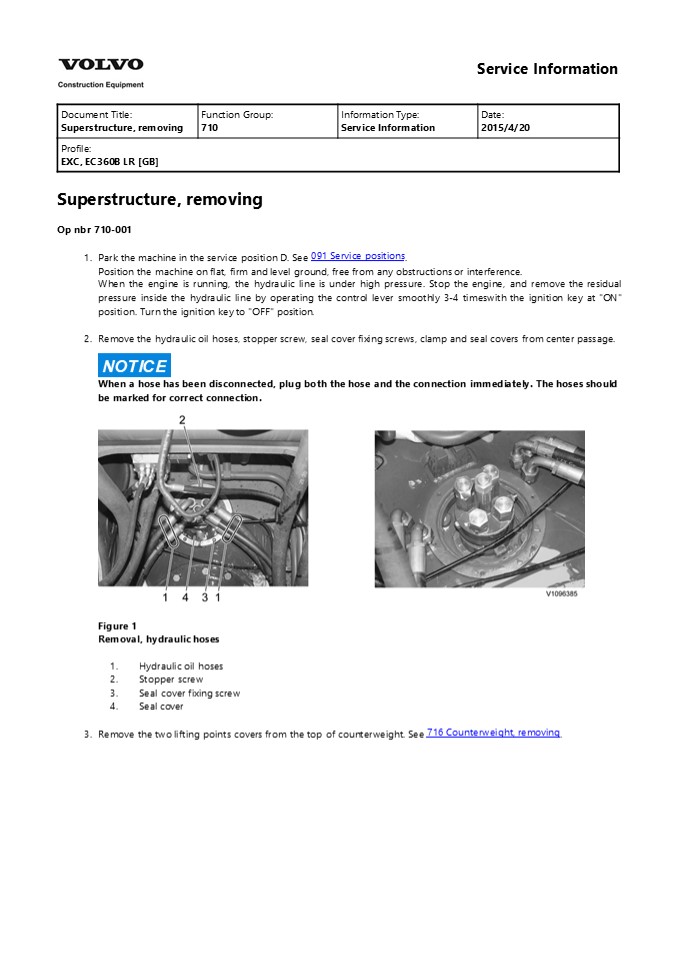
the ignition key to "OFF" position. - Remove the hydraulic oil hoses, stopper screw,
seal cover fixing screws, clamp and seal covers
from center passage.
NOTICE
When a hose has been disconnected, plug both the
hose and the connection immediately. The hoses
should be marked for correct connection.
- Figure 1
- Removal, hydraulic hoses
- Hydraulic oil hoses
- Stopper screw
- Seal cover fixing screw
- Seal cover
- 3. Remove the two lifting points covers from the
top of counterweight. See 716 Counterweight,
removing.
2
Figure 2 Removal, lifting points covers (1)
WARNING
4.
Risk of personal injury. Very heavy object.
WARNING
The parts are heavy. Take appropriate safety
cautions when handling them.
WARNING
Never lift the machine with a person in the cab.
WARNING
Always use classified cables, lifting straps,
shackles and hooks with sufficient lifting
capacity. Hold the superstructure with wire ropes
(cables). Check the superstructure weight. See
710 Machine weight, specifications. Check the
wire ropes length (cables). Refer to the
operators manual for further operation or cab in
lifting machine decal. See Operating
instructions, Transporting machine, Lifting
machine.
- Figure 3
- Lifting superstructure
- Wire rope (cable)
- Superstructure
- Undercarriage
3
Figure 4 Lifting points NOTE! As shown in the
decal for lifting, connect lifting wire ropes
(cables) or slings with sufficient strength for
the machine weight at the lifting points
correctly. After installation of all hoisting
equipment, lift the machine a little to check its
balance, if satisfactory, lift it slowly and
evenly. 5. Remove the superstructure mounting
screws from the swing ring gear.
- Figure 5
- Removal, superstructure mounting screws
- Superstructure mounting screw
- Swing ring gear
WARNING
6.
4
https//www.ebooklibonline.com Hello dear
friend! Thank you very much for reading. Enter
the link into your browser. The full manual is
available for immediate download. https//www.ebo
oklibonline.com
5
The superstructure is heavy. Pay attention to
safe footing and the area around the crane before
proceeding to remove or install the
superstructure. Remove the superstructure slowly
and lower onto the 4 jacks safely. Maintain good
visibility of the machine at all times during the
lift. And continuously check that the machine is
level.
Figure 6 Removal, lifting superstructure (1)
6
Service Information
Document Title Superstructure, installing Function Group 710 Information Type Service Information Date 2015/4/20
Profile EXC, EC360B LR GB Profile EXC, EC360B LR GB Profile EXC, EC360B LR GB Profile EXC, EC360B LR GB
Superstructure, installing Op nbr 710-002
WARNING
1.
Risk of personal injury. Very heavy object.
WARNING
The parts are heavy. Take appropriate safety
cautions when handling them.
WARNING
Never lift the machine with a person in the cab.
WARNING
Always use classified cables, lifting straps,
shackles and hooks with sufficient lifting
capacity. Hold the superstructure with wire ropes
(cables). Check the superstructure weight. See
710 Machine weight, specifications. Wire ropes
length (cables). Refer to the operators manual
for further operation or cab in lifting machine
decal. See Operating instructions, Transporting
machine, Lifting machine.
- Figure 1
- Lifting superstructure
- Wire rope (cable)
- Superstructure
- Undercarriage
7
Figure 2 Lifting points NOTE! As shown in the
decal for lifting, connect lifting wire ropes
(cables) or slings with sufficient strength for
the machine weight at the lifting points
correctly. After installation of all hoisting
equipment, lift the machine a little to check its
balance, if satisfactory, lift it slowly and
evenly. 2. Thoroughly clean the mounting
surface. Before replacing the superstructure,
apply sealing compound to the mounting
surface. NOTE! If impurities remain, adhesion
with bond agent is not good.
- Figure 3
- Clean the mounting surface
- Clean the mounting surface
- Sealing compound
8
WARNING
3.
The superstructure is heavy. Pay attention to
safe footing and the area around the crane before
proceeding to remove or install the
superstructure. Lift the superstructure and
install it to the swing ring gear. Maintain good
visibility of the machine at all times during the
lift. And continuously check that the machine is
level. NOTE! Match the S mark (soft zone
position) on inner race and the plug on outer
race.
- Figure 4
- Installation, superstructure
- Superstructure
- Swing ring gear
- S mark inner race (soft zone position)
- Plug outer race
- 4. Install the superstructure mounting screws from
the swing ring gear. Tightening torque. See 492
Swing ring gear, description. Apply Loctite 277
or equivalent locking fluid.
Figure 5
9
- Installation, superstructure mounting screws
- Superstructure mounting screw
- Swing ring gear
- 5. Remove the wire rope (cable) at the lifting
points. - Install the seal covers, seal cover fixing
screws, stopper screw, clamp and hydraulic oil
hoses from center passage. Tightening torque,
seal cover fixing screw 22.6 1.96 Nm (2.3 0.2
kgf m) (16.6 1.4 lbf ft) - Apply Loctite 277 or equivalent locking fluid.
- Figure 6
- Installation, hydraulic hoses
- Hydraulic oil hoses
- Stopper screw 242.2 24.5 Nm (24.7 2.5 kgf m)
(178.3 18 lbf ft) - Seal cover fixing screw
- Seal cover
- Stopper screw 15 mm (0.59 inch)
- Install the two lifting points covers from the top
of counterweight. See tightening torque. 716
Counterweight, tightening torques.
Figure 7 Installation, lifting points covers
(1) 7. Check the operation of the swing,
hydraulic oil hoses and swing ring gear mounting
screws.
10
Service Information
Document Title Counterweight, description Function Group 716 Information Type Service Information Date 2015/4/20
Profile EXC, EC360B LR GB Profile EXC, EC360B LR GB Profile EXC, EC360B LR GB Profile EXC, EC360B LR GB
Go back to Index Page Counterweight,
description Casting type The counterweight is a
counterbalancing weight that is located at the
rear of the machine. The counterweight is
designed in order to give the machine extra
weight in the back end in order to counter the
weight that is located at the front of the
machine, in particular the boom and dipper arm.
Figure 1 Counterweight, structure
1 Counterweight 6 Shim 11 Screw
2 Cover 7 Lock nut 12 Screw
3 Plate 8 Nut 13 Plug
4 Screw 9 Screw 14 Reflector mounting
5 Spacer 10 Reflector
11
Service Information
Document Title Counterweight, description Function Group 716 Information Type Service Information Date 2015/4/20
Profile EXC, EC360B LR GB Profile EXC, EC360B LR GB Profile EXC, EC360B LR GB Profile EXC, EC360B LR GB
Go back to Index Page Counterweight,
description Fabrication type The counterweight is
a counterbalancing weight that is located at the
rear of the machine. The counterweight is
designed in order to give the machine extra
weight in the back end in order to counter the
weight that is located at the front of the
machine, in particular the boom and dipper arm.
Figure 1 Counterweight, structure
1 Body 2 Plate 3 Reflector 4 Cover
5 Stopper 6 Base 7 Side plate 8 Under cover
12
Service Information
Document Title Support information Function Group 716 Information Type Service Information Date 2015/4/20
Profile EXC, EC360B LR GB Profile EXC, EC360B LR GB Profile EXC, EC360B LR GB Profile EXC, EC360B LR GB
Support information Removal counterweight
support, description
Figure 1 Removal counterweight support
1 Removal counterweight support (Weight 800 kg, 1764 lbs)
2 Removal counterweight cylinder
3, 4 Support mounting screws Tightening torque 1324 49 Nm (135 5 kgf m) (975 36 lbf ft)
5 GAP LH and RH 12.5 mm (0.492 inch)
13
Service Information
Document Title Counterweight, removing Function Group 716 Information Type Service Information Date 2015/4/20
Profile EXC, EC360B LR GB Profile EXC, EC360B LR GB Profile EXC, EC360B LR GB Profile EXC, EC360B LR GB
Go back to Index Page Counterweight,
removing Casting type Op nbr 71601
WARNING
The counterweight is heavy. Take care in
performing removal. To lift the counterweight,
use certified wire ropes in good condition, of
adequate load rating and length.
WARNING
- Heavy lift. Make sure that no persons are under
the counterweight when it is lifted. - NOTE!
- The counterweight weighs 6700 kg (14771 lbs).
- Position the machine on flat, firm and level
ground, free from any obstructions or
interference. Position the boom and arm with the
bucket on the ground. - Attach wire slings (B) to lifting eyes (A) and
eye bolt (C) at the top surface of the
counterweight and lift until there is no slack in
the wire ropes.
Figure 1 Attach wire slings 3. Remove screws (9)
using socket wrench.
14
Figure 2 Removal, screws 4. Remove lock nut (7)
and nut (8), using socket wrench or power wrench.
Figure 3 Removal, lock nut 5. Lift the
counterweight just a little, and after confirming
safety all around, lift it up and out.
15
Service Information
Document Title Counterweight, removing Function Group 716 Information Type Service Information Date 2015/4/20
Profile EXC, EC360B LR GB Profile EXC, EC360B LR GB Profile EXC, EC360B LR GB Profile EXC, EC360B LR GB
Go back to Index Page Counterweight,
removing Fabrication type Op nbr 716-001
WARNING
The counterweight is heavy. Take care in
performing removal. To lift the counterweight,
use certified wire ropes in good condition, of
adequate load rating and length.
WARNING
- Heavy lift. Make sure that no persons are under
the counterweight when it is lifted. - Position the machine on flat, firm and level
ground, free from any obstructions or
interference. Position the boom and arm with the
bucket on the ground. - Place the machine in the Service position B. see
091 Service positions. - Remove the plugs on the top surface of the
counterweight and install eye bolts (2) - Attach wire slings (1) to eye bolts (2) and lift
until there is no slack in the wire ropes. - NOTE!
- Recommendation length of wire slings to keep
counterweight level. - A 2100 mm (82.7 inch), B 2050 mm (80.7 inch)
Figure 1
16
- Remove the engine room under cover then remove
screw (7), spring washer (8) and plain washer
(9). - Remove screw (6), spacer (5).
- Lift the counterweight just a little, and after
confirming safety all around, lift it up and out. - Remove the counterweight and securely support the
counterweight. - Install the engine room under cover.
17
Service Information
Document Title Counterweight, fitting Function Group 716 Information Type Service Information Date 2015/4/20
Profile EXC, EC360B LR GB Profile EXC, EC360B LR GB Profile EXC, EC360B LR GB Profile EXC, EC360B LR GB
Go back to Index Page Counterweight,
fitting Casting type Op nbr 716-002
WARNING
Lift the counterweight just a little, and after
confirming safety and horizontal position,
proceed to install it.
WARNING
- Heavy lift. Make sure that no persons are under
the counterweight when it is lifted. - Position the machine on flat, firm and level
ground, free from any obstructions or
interference. Position the boom and arm with the
bucket on the ground. - Attach wire slings to the lifting eyes at the top
surface of the counterweight and lift to the
desired position. - NOTE!
- The ratio of the length for lifting cables (A)
and balance cables (C) is 1 0.7.
- Figure 1
- Installation, counterweight
- Lifting cables
- Eye bolt
- Balance cable
- 3. Tighten nut (8) to the specified torque and
then tighten lock nut (7). - NOTE!
- Apply loctite 277 on threads of screws (4).
18
Suggest For more complete manuals. Please go to
the home page. https//www.ebooklibonline.com If
the above button click is invalid. Please
download this document first, and then click the
above link to download the complete manual. Thank
you so much for reading
19
NOTE! Maintain the clearance (left and right)
within 7 - 13 mm.
Figure 2 Tightening, lock nut 4. Remove the
engine room under cover and match the screws
hole. and then install and tighten screws (9) to
the specified torque. See tightening torque, 716
Counterweight, tightening torques. NOTE! Apply
loctite 277 on threads of screws (9).
- Figure 3 Tightening, screws
- install the engine room under cover.
- Install the two covers and remove the eye bolts.
Assemble the plug to the top of counterweight.
20
Service Information
Document Title Counterweight, fitting Function Group 716 Information Type Service Information Date 2015/4/20
Profile EXC, EC360B LR GB Profile EXC, EC360B LR GB Profile EXC, EC360B LR GB Profile EXC, EC360B LR GB
Go back to Index Page Counterweight,
fitting Fabrication type Op nbr 716-002
WARNING
Lift the counterweight just a little, and after
confirming safety and horizontal position,
proceed to install it. 1. Position the machine
on flat, firm and level ground, free from any
obstructions or interference. Position the boom
and arm with the bucket on the ground. Place the
machine in the Service position B. see 091
Service positions.
- Figure 1
- Engage the control lockout lever securely.
- Clean the surfaces of counterweight mounting
before fitting. - Remove the engine room under cover.
- NOTE!
- Recommendation length of wire slings to keep
counterweight level. - A 2100 mm (82.7 inch), B 2050 mm (80.7 inch)
- Lower the counterweight to the mounting face at
the rear of the superstructure.
21
https//www.ebooklibonline.com Hello dear
friend! Thank you very much for reading. Enter
the link into your browser. The full manual is
available for immediate download. https//www.ebo
oklibonline.com
Recommended
CrystalGraphics Presentations


