
CASE IH MXM190 Tractor Service Repair Manual Instant Download
Title:
CASE IH MXM190 Tractor Service Repair Manual Instant Download
Description:
CASE IH MXM190 Tractor Service Repair Manual Instant Download –
Number of Views:0
Title: CASE IH MXM190 Tractor Service Repair Manual Instant Download
1
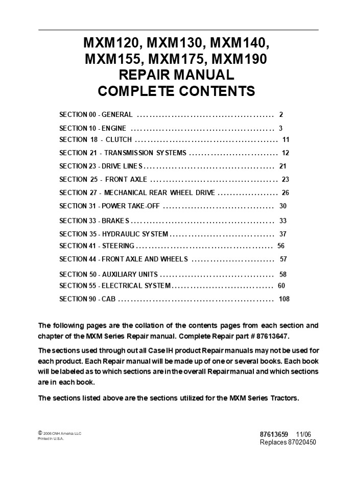
MXM120, MXM130, MXM140, MXM155, MXM175, MXM190
REPAIR MANUAL COMPLETE CONTENTS
SECTION 00 - GENERAL .............................
............... 2 SECTION 10 - ENGINE
..............................................
3 SECTION 18 - CLUTCH ............................
.................. 11 SECTION 21 - TRANSMISSION
SYSTEMS ............................. 12 SECTION
23 - DRIVE LINES .................................
......... 21 SECTION 25 - FRONT AXLE
......................................... 23
SECTION 27 - MECHANICAL REAR WHEEL DRIVE
.................... 26 SECTION 31 - POWER
TAKE-OFF ....................................
30 SECTION 33 - BRAKES ...........................
................... 33 SECTION 35 - HYDRAULIC
SYSTEM ..................................
37 SECTION 41 - STEERING .........................
................... 56 SECTION 44 - FRONT AXLE
AND WHEELS ........................... 57 SECTION
50 - AUXILIARY UNITS .............................
........ 58 SECTION 55 - ELECTRICAL SYSTEM
................................. 60 SECTION 90
- CAB ............................................
...... 108 The following pages are the collation
of the contents pages from each section and
chapter of the MXM Series Repair manual. Complete
Repair part 87613647. The sections used through
out all Case IH product Repair manuals may not be
used for each product. Each Repair manual will
be made up of one or several books. Each book
will be labeled as to which sections are in the
overall Repair manual and which sections are in
each book. The sections listed above are the
sections utilized for the MXM Series Tractors.
? 2006 CNH America LLC Printed In U.S.A.
87613659 11/06 Replaces 87020450
2
SECTION 00 - GENERAL - CHAPTER 1
1
SECTION 00 - GENERAL Chapter 1 -
General CONTENTS
Description Page General Instructions
..................................................
.......... 3 Important Notice ....................
........................................
3 Shimming .......................................
........................... 3 Rotating Shaft
Seals ............................................
............ 3 O Rings ...........................
........................................
3 Sealers ........................................
............................ 3 Bearings
..................................................
................. 3 Spring Pins
..................................................
.............. 3 Precautionary Notice
..................................................
...... 4 Equipment Notice ........................
................................... 4 Spare Parts
Notice ...........................................
............... 4 General Notices
..................................................
.......... 4 Health and Safety ...................
...........................................
5 Health and Safety Precautions
................................................
5 Precautionary Statements .......................
.............................. 14 Safety
..................................................
.................... 15 The Tractor
..................................................
............ 15 Driving the Tractor
..................................................
...... 15 Operating the Tractor
..................................................
.... 15 Operating the PTO ........................
................................ 16 Servicing the
Tractor ..........................................
............ 16 Diesel Fuel ......................
........................................ 17 ROPS
..................................................
................. 17 Ecology and the Environment
..................................................
18 Precautions ..................................
............................ 18 Minimum Hardware
Tightening Torques ...............................
.......... 19 Federal Emissions Warranty
..................................................
. 21 California Emission Control Warranty
Statement .................................. 22
Lubricants and Coolants ..........................
............................ 24 Sulphur in Fuel
..................................................
......... 24 Biodegradable Transmission, Drive
Axle, Hub, and Hydraulic System Oil ......... 24
Section
3
SECTION 00 - GENERAL - CHAPTER 1 WARNING WARNING
2
All maintenance and repair work described in
this manual must be performed exclusively by
CASE IH service technicians in strict accordance
with the instructions given and using any
specific tools necessary.
The Manufacturer and all organizations belong-
ing to the Manufacturer's distribution network,
including but not restricted to national,
regional or local distributors, will accept no
responsibility for personal injury or damage to
property caused by abnormal function of parts
and/or compo- nents not approved by the
Manufacturer, including those used for
maintenance and/or repair of the product
manufactured or marketed by the Manufacturer. In
any case, the product manufactured or marketed
by the Manufacturer is covered by no guarantee
of any kind against personal injury or damage to
property caused by abnormal function of parts
and/or components not approved by the
Manufacturer.
WARNING
Anyone who performs the operations described
herein without strictly following the
instructions is personally responsible for
resulting injury or damage to property.
4
https//www.ebooklibonline.com Hello dear
friend! Thank you very much for reading. Enter
the link into your browser. The full manual is
available for immediate download. https//www.eb
ooklibonline.com
5
SECTION 00 - GENERAL - CHAPTER 1
3
GENERAL INSTRUCTIONS
IMPORTANT NOTICE All maintenance and repair
operations described in this manual should be
carried out exclusively by the authorized
workshops. All instructions detailed should be
carefully observed and special equipment
indicated should be used if necessary. Everyone
who carries out service operations described
without carefully observing these prescrip-
tions will be directly responsible of deriving
damages.
- Take care to insert the seal perpendicularly to
its seat while you are pressing it. Once the
seal is settled, ensure that it contacts the
thrust element, if required - To prevent damaging the sealing lip against the
shaft, place a suitable protection during
installation.
O RINGS Lubricate the O rings before inserting
them into their seats. This will prevent the O
rings from roll over and twisting during
mounting, which will jeopardize sealing.
SHIMMING At each adjustment, select adjusting
shims, measure them individually using a
micrometer and then sum up recorded values. Do
not rely on measuring the whole shimming set,
which may be incorrect, or on the rated value
indicated for each shim.
SEALERS Apply silicone/gasket eliminator over the
mating surfaces marked with an X. Before
applying the sealer, prepare the surface as
follows
ROTATING SHAFT SEALS To correctly install
rotating shaft seals, observe the following
instructions
- remove possible scales using a metal brush
- thoroughly degrease the surfaces using one of
the following cleaning agents trichlorethylene,
diesel fuel or a water and soda solution.
- Let the seal soak into the same oil as it will
seal for at least half an hour before mounting - Thoroughly clean the shaft and ensure that the
shaft working surface is not damaged - Place the sealing lip towards the fluid. In case
of a hydrodynamic lip, consider the shaft
rotation direction and orient grooves in order
that they deviate the fluid towards the inner
side of the seal - Coat the sealing lip with a thin layer of
lubricant (oil rather than grease) and fill the
gap between the sealing lip and the dust lip of
double lip seals with grease - Insert the seal into its seat and press it down
using a flat punch. Do not tap the seal with a
hammer or a drift
BEARINGS It is advisable to heat the bearings to
80? to 90?C (176? to 194?F) before mounting them
on their shafts and cool them down before
inserting them into their seats with external
tapping.
SPRING PINS When mounting split socket spring
pins, ensure that the pin notch is oriented in
the direction of the effort to stress the
pin. Spiral spring pins should not be oriented
during installation.
6
SECTION 00 - GENERAL - CHAPTER 1
5
HEALTH AND SAFETY
HEALTH AND SAFETY PRECAUTIONS Many of the
procedures associated with vehicle maintenance
and repair involve physical hazards or other
risks to health. This section lists, alphabeti-
cally, some of these hazardous operations and the
materials and equipment associated with them.
The precautions necessary to avoid these hazards
are identified. The list is not exhaustive and
all operations and procedures and the handling
of materials, should be carried out with health
and safety in mind.
Mixing should only be carried out in well
ventilated areas as harmful or toxic volatile
chemicals may be released. Skin contact with
uncured resins and hardeners can result in
irritation dermatitis and absorption of toxic
or harmful chemicals through the skin. Splashes
can damage the eyes. Provide adequate
ventilation and avoid skin and eye contact.
Follow manufacturers instructions.
Anaerobic, Cyanoacrylate and other Acrylic
Adhesives Many are irritant, sensitizing or
harmful to the skin. Some are eye
irritants. Skin and eye contact should be avoided
and the manufacturers instructions
followed. Cyanoacrylate adhesives (super-glues)
must not contact the skin or eyes. If skin or
eye tissue is bonded cover with a clean moist
pad and get medical attention. do not attempt to
pull tissue apart. Use in well ventilated areas
as vapors can cause irritation of the nose and
eyes. For two-pack systems see Resin based
adhesives/ sealers.
ACIDS AND ALKALIS - see Battery acids, e.g.
caustic soda, sulfuric acid. Used in batteries
and cleaning materials. Irritant and corrosive to
the skin, eyes, nose and throat. Causes
burns. Avoid splashes to the skin, eyes and
clothing. Wear suitable protective gloves and
goggles. Can destroy ordinary protective
clothing. Do not breathe mists. Ensure access to
water and soap is readily available for
splashing accidents.
ADHESIVES AND SEALERS - see Fire Highly
Flammable, Flammable, combustible. Generally
should be stored in No Smoking areas
cleanliness and tidiness in use should be
observed, e.g. disposable paper covering benches
should be dispensed from applicators where
possible contain- ers, including secondary
containers, should be labelled. Solvent based
Adhesives/Sealers - See Solvents. Follow
manufacturers instructions. Water based
Adhesives/Sealers Those based on polymer
emulsions and rubber lattices may contain small
amounts of volatile toxic and harmful chemicals.
Skin and eye contact should be avoided and
adequate ventilation provided during use. Follow
manufacturers instructions. Resin based
Adhesives/Sealers - e.g., epoxide and
formaldehyde resin based.
Isocyanate (Polyurethane) Adhesives/ Sealers
- see Resin based Adhesives. Individuals
suffering from asthma or respiratory allergies
should not work with or near these materials as
sensitivity reactions can occur. Any spraying
should preferably be carried out in exhaust
ventilated booths removing vapors and spray
droplets from the breathing zone. Individuals
working with spray applications should wear
supplied air respirators.
ANTIFREEZE - see Fire, Solvents e.g.,
Isopropanol, Ethylene Glycol, Methanol. Highly
Flammable, Flammable, Combustible. Used in
vehicle coolant systems, brake air pressure
systems, screenwash solutions. Vapors given off
from coolant antifreeze (glycol) arise only when
heated. Antifreeze may be absorbed through the
skin in toxic or harmful quantities. Antifreeze
if swallowed is fatal and medical attention must
be found immediately.
7
6 SECTION 00 - GENERAL - CHAPTER 1
ARC WELDING - see Welding.
The effects of excessive exposure to chemicals
may be immediate or delayed briefly experienced
or permanent cumulative superficial life
threatening or may reduce life-expectancy.
BATTERY ACIDS - see Acids and Alkalis. Gases
released during charging are explosive. Never
use naked flames or allow sparks near charging
or recently charged batteries.
Dos Do remove chemical materials from the skin
and clothing as soon as practicable after
soiling. Change heavily soiled clothing and
have it cleaned. Do carefully read and observe
hazard and precaution warnings given on material
containers (labels) and in any accompanying
leaflets, poster or other instructions. Material
health and safety data sheets can be obtained
from Manufacturers. Do organize work practices
and protective clothing to avoid soiling of the
skin and eyes breathing vapors/aerosols/dusts/fu
mes inadequate container labelling fire and
explosion hazards. Do wash before job breaks
before eating, smoking, drinking or using toilet
facilities when handling chemical materials. Do
keep work areas clean, uncluttered and free of
spills. Do store according to national and local
regulations. Do keep chemical materials out of
reach of children.
BRAKE AND CLUTCH FLUIDS (Polyalkylene Glycols) -
see Fire. Combustible. Splashes to the skin and
eyes are slightly irritating. Avoid skin and eye
contact as far as possible. Inhalation of vapor
hazards do not arise at ambient temperatures
because of the very low vapor pressure.
BRAZING - see Welding.
CHEMICAL MATERIALS - GENERAL - see Legal
Aspects. Chemical materials such as solvents,
sealers, adhesives, paints, resin foams, battery
acids, antifreeze, brake fluids, oils and grease
should always be used with caution and stored
and handled with care. They may be toxic,
harmful, corrosive, irritant or highly
inflammable and give rise to hazardous fumes and
dusts.
8
SECTION 10 - ENGINE - CHAPTER 1
1
SECTION 10 - ENGINE Chapter 1 - Separating and
Removing The Engine CONTENTS
Description Page Tightening Torques
..................................................
.......... 2 Special Tools .......................
..........................................
3 Separating and Removing the Engine
............................................
4 Front Axle and Support .........................
............................ 4 Separating Front
Axle and Support from Engine .....................
....... 4 Installation ..........................
................................. 12 Engine and
Front Support ....................................
.............. 14 Separating Engine and Front
Support from Transmission ................... 14
Installation .....................................
...................... 20 Engine
..................................................
................ 21 Removal ......................
.......................................
21 Installation ..................................
......................... 24
Section
9
2
SECTION 10 - ENGINE - CHAPTER 1
TIGHTENING TORQUES
1
10
SECTION 10 - ENGINE - CHAPTER 1
3
The following general nut and bolt installation
torque requirements (lubricated) apply to any
operation not previously listed.
INCH SERIES ft-lb N?m
1/4 -- 20 8 11
1/4 -- 28 8 11
5/16 --18 14 19
5/16 --24 17 23
3/4 -- 16 23 31
3/4 -- 24 33 45
7/16 --14 48 65
7/16 --20 55 75
1/2 -- 13 65 88
1/2 -- 20 75 102
9/16 --18 90 122
5/6 --18 138 187
SPECIAL TOOLS (Prior Tool Numbers, where
applicable, shown in brackets)
Description Tool Number
Engine Lifting Brackets 82932534 and 82852825
Engine revolving stand 380000301 or 380000361
Engine overhaul brackets kit - Use with 380000301 380000313
Tractor splitting kit CAS.30009A or 380000569
Engine support brackets (for use with tractor splitting kit) 380000500
11
4 SECTION 10 - ENGINE - CHAPTER 1 SEPARATING AND
REMOVING THE ENGINE FRONT AXLE AND
SUPPORT Separating Front Axle and Support from
Engine 1. Disconnect battery ground lead (1)
and then dis- connect the positive lead (2).
2
2
2. If front weights are fitted to the front of
the tractor remove using suitable hoist with
adequate safe working load.
3
3. Disconnect air to air intercooler pipes.
4
4. Disconnect transmission oil cooler hoses (1)
and drain oil into clean container.
1
5
12
SECTION 10 - ENGINE - CHAPTER 1
5
5. Remove clips (1) securing air conditioning
con- densor tubes to side of radiator.
6
6. Withdraw condensor from front of radiator and
place in a safe place on side of engine. NOTE
Never disconnect the hoses to the condenser
unless the air conditioning system has been
evacuated as described in Section 50 of this
Repair Manual.
7
7. Drain the cooling system fluid into a clean
con- tainer and disconnect the radiator hoses.
Dis- connection of the radiator lower hose
provides a suitable drain point. Place a large
clean tray un- der the vehicle to capture the
fluid for future use.
8
13
6 SECTION 10 - ENGINE - CHAPTER 1 Tractors fitted
with suspended front axle 1. Depressurize the
suspension system by rotating screw on top of
the suspension load sense un- load valve
clockwise. When the tractor has low- ered
completely onto the front support stops ro- tate
the screw counterclockwise to normal operating
position.
9
2. Disconnect the pipes to the front axle
suspension cylinders. WARNING On tractors with
suspended front axle ensure suspension has been
fully lowered as described above before
disconnecting suspension cylinder hoses.
10
3. Remove suspension pipes and guard.
11
4. Remove the rear pivot block bolts.
12
14
SECTION 10 - ENGINE - CHAPTER 1
7
5. Position trolley jack beneath front support
and raise front of tractor.
13
6. Position a suitable piece of strong timber be-
tween oil pan and suspension arm.
14
7. In a controlled manner lower the front of
the trac- tor to the ground. The lowering action
will cause the suspension arm pivot block to
separate from the transmission casing.
15
8. Disconnect and remove front wheel drive shaft
universal joint.
16
15
8
SECTION 10 - ENGINE - CHAPTER 1
9. Remove engine side rails
17
10. Disconnect the 2 steering tubes and
differential lock tube from the right hand
side. NOTE If front axle brakes are fitted,
disconnect the common brake pipe to the axle.
18
Tractors fitted with standard FWD axle 1. Remove
engine side rails where fitted.
19
2. Remove front wheel drive shaft guard, if
fitted.
20
16
SECTION 10 - ENGINE - CHAPTER 1
9
3. Remove drive shaft. NOTE The type of
driveshaft fitted is dependant on type of axle
installed.
21
4. Disconnect power steering hoses (1) and (2) on
each side of the tractor. Disconnect
differential lock hose (3). NOTE Pipework will
vary depending on type of axle installed. NOTE
If front axle brakes are fitted, disconnect the
common brake pipe to the axle.
22
5. Inspect the harness connections between the
engine and front support and disconnect where
necessary to enable the front support and axle to
be separated from the engine. NOTE The type
and number of connections to be disconnected is
dependant on the build option and ancillary
equipment fitted to the front of the tractor.
23
17
10
SECTION 10 - ENGINE - CHAPTER 1
24
- Position splitting kit (3) 380000569 or
- CAS.3009A beneath tractor.
- Use supports part of kit to support the transmis-
sion (2) on the splitting stand. - On tractors with suspended front axle support
the suspension arm using the wheeled splitting
trolley (1) which is part of tractor splitting
kit. - NOTE On tractors not fitted with suspended front
axle the engine may be supported using brackets
380000500 and wheeled splitting trolley as
illustrated in Figure 54.
18
SECTION 10 - ENGINE - CHAPTER 1
11
9. Position wooden wedges (1) between the front
axle and support. These prevent articulation of
the axle and must be used.
25
10. Using spreader bar and suitable chains or
slings attach the front and rear of the support
assembly to a moveable overhead
hoist. WARNING Always ensure the support is
adequately supported and will remain stable when
separated from the engine. Failure to provide
adequate support may cause the assembly to be
unstable with possible personal injury if the
support tips forwards or backwards.
26
- Remove front support to engine securing bolts
and separate front support from the engine. - Separate front support from engine.
27
13. Support assembly on axle stands at front and
rear of support.
28
19
12 SECTION 10 - ENGINE - CHAPTER 1 14. On
tractors with suspended front axle position
stands under the support and suspension arm.
29
15. Identify for use during reassembly the two
shims positioned between the engine sump and
front support.
30
Installation The following procedure must be
observed when reassembling the front support to
the engine. 1. Install spacers on two outer
mounting bolts (1) on either side of the engine.
31
- Ensure shims, Figure 30 removed during disas-
sembly are repositioned in the same location as
when disassembled. - NOTE If a new front support or the engine oil
pan has been removed and replaced during
overhaul it is necessary to recalculate the new
shim thickness to be installed using the
following procedure. - Install 4.5 mm yellow shim part number 82026240
onto each of the engine mounting studs.
32
20
SECTION 10 - ENGINE - CHAPTER 1
13
- Assemble front support to engine and torque the
four upper retaining bolts to specified torque - Using feeler gauges measure space between each
shim and front support.
33
6. Add feeler gauge dimension to the 4.1mm shim
thickness already installed and select appropri-
ate shims from following list.
Color Code Shim Thickness Part Number
Yellow 4.5 mm 82026240
Green 4.8 mm 82026241
Red 5.1 mm 82026242
Blue 5.4 mm 82026243
White 5.7 mm 82026244
Black 6.0 mm 82026245
Pink 6.3 mm 82026246
Light Blue 6.6 mm 82026247
Gold 6.9 mm 82026248
Lime 7.2 mm 82026249
Orange 7.5 mm 82026250
Blue/Grey 7.8 mm 82026251
- Separate front support from engine and replace
4.1mm shims with shims of calculated thickness. - Reinstall front support and tighten retaining
bolts to specified torques.
21
14 SECTION 10 - ENGINE - CHAPTER 1 ENGINE AND
FRONT SUPPORT Separating Engine and Front
Support from Transmission 1. Disconnect
battery. The ground lead (1) should be
disconnected first.
34
2. Disconnect hood harness connector and remove
exhaust muffler and hood.
35
3. To ensure correct reassembly identify steering
pipes (1), and transmission oil cooler pipes
(3), and disconnect. Similarly disconnect four
wheel drive diff lock pipe (2).
36
4. Remove air brake unload valve (1) where fitted.
37
22
SECTION 10 - ENGINE - CHAPTER 1
15
5. Disconnect harness and remove starter motor.
38
6. Disconnect brake tubes to master cylinder.
39
7. Disconnect main harness to engine harness
con- nectors located beneath front of cab.
40
8. Disconnect air conditioning at quick release
cou- plers on left hand side of engine.
41
23
16 SECTION 10 - ENGINE - CHAPTER 1 9. Disconnect
water pipe to heater shut off tap at rear of
cylinder head. Similarly disconnect water hose
to cab near the engine bellhousing.
42
Tractors with Suspended front axle 1.
Depressurize the suspension system by rotating
screw on side of suspension load sense unload
valve clockwise. When the tractor has lowered
completely onto the front support stops rotate
the screw fully counterclockwise to normal
operating position.
43
2. Disconnect the pipes to the front axle
suspension cylinders. WARNING On tractors with
suspended front axle ensure suspension has been
fully lowered as described above before
disconnecting suspension cylinder hoses.
44
3. Remove suspension pipes and guard.
45
24
SECTION 10 - ENGINE - CHAPTER 1
17
4. Remove the rear pivot block bolts.
46
5. Position trolley jack beneath front support
and raise front of tractor.
47
6. Position a suitable piece of strong timber (1)
be- tween oil pan and suspension arm.
48
7. In a controlled manner lower the front of
the trac- tor to the ground. The lowering action
will cause the suspension arm pivot block to
separate from the transmission casing.
49
25
18 SECTION 10 - ENGINE - CHAPTER 1 8. Disconnect
and remove front wheel drive shaft universal
joint.
50
Tractors with Standard FWD Axle 1. Remove front
wheel drive propshaft guard and propshaft NOTE
The type of driveshaft fitted is dependant on
type of axle installed
51
2. Remove driveshaft flange, where fitted.
52
3. Remove engine side rails
53
26
SECTION 10 - ENGINE - CHAPTER 1
19
54
- Position splitting kit (3) 380000569 or
- CAS.30009A beneath tractor.
- Use supports, part of kit to support the
transmis- sion (2) on the splitting stand. - Remove 2 oil pan bolts from each side of the en-
gine and install engine support brackets (1)
380000500 between engine and wheeled split- ting
trolley, part of tractor splitting kit.
27
20
SECTION 10 - ENGINE - CHAPTER 1
7. Position wooden wedges (1) between the front
axle and support. These prevent articulation of
the axle and must be used.
55
8. Remove cover plate bolt (1) on lower left hand
side of engine.
56
- Check that all necessary hoses tubes and con-
nectors have been disconnected. It may be nec-
essary to disconnect additional items due to oth-
er optional equipment that has been installed on
the tractor. - Re check that engine and transmission are safe-
ly supported on the splitting stand then remove
engine to transmission buckle up bolts. - Carefully wheel the front support and engine as-
sembly from the transmission.
57
- Installation
- Installation is removal procedure in reverse.
- Tighten all buckle up bolts to correct torque.
28
SECTION 10 - ENGINE - CHAPTER 1
21
ENGINE Removal 1. Separate the front axle and
support from the en- gine as described on Page
4. NOTE The engine can also be removed if the
engine has initially been separated from the
transmission as described on Page 14. Care must
be taken to ensure the engine, axle and front
support are safely sup- ported before separating
the axle and front support from the engine.
58
2. Remove the air cleaner system.
59
3. To ensure correct reassembly identify steering
pipes (1) and transmission oil cooler pipes (3)
and disconnect. Similarly disconnect four wheel
drive differential lock pipe (2).
60
4. Remove air brake unload valve (1) where fitted.
61
29
22
SECTION 10 - ENGINE - CHAPTER 1
5. Disconnect harness and remove starter motor.
62
6. Disconnect brake tubes to master cylinder.
63
7. Disconnect main harness to engine harness
con- nectors located beneath front of cab.
64
8. Disconnect air conditioning at quick release
cou- plers on left hand side of engine.
65
30
MORE MANUALS https//www.ebooklibonline.com/
Suggest If the above button click is invalid.
Please download this document first, and then
click the above link to download the complete
manual. Thank you so much for reading
31
SECTION 10 - ENGINE - CHAPTER 1
23
9. Remove air conditioning compressor, condens-
er, receiver dryer and pipework from engine as a
complete assembly without disconnecting pipe-
work. IMPORTANT If it is not possible to remove
air condi- tioning components as a complete
assembly the air conditioning system must be
evacuated as de- scribed in Section 50 of this
Repair Manual. It is an offence to discharge air
conditioning sys- tems into the atmosphere.
66
10. Disconnect water pipe to heater shut off tap
at rear of cylinder head. Similarly disconnect
water hose to cab near the engine bellhousing.
67
11. Attach lifting brackets 82932534 and
82852825 to the engine.
68
- Attach suitable sling or chains to overhead
hoist and support engine. - Remove engine to transmission buckle up bolts
and remove engine from transmission.
69
32
https//www.ebooklibonline.com Hello dear
friend! Thank you very much for reading. Enter
the link into your browser. The full manual is
available for immediate download. https//www.eb
ooklibonline.com
Recommended
CrystalGraphics Presentations


