
CASE CX180B Crawler Excavator Service Repair Manual Instant Download
Title:
CASE CX180B Crawler Excavator Service Repair Manual Instant Download
Description:
CASE CX180B Crawler Excavator Service Repair Manual Instant Download –
Number of Views:0
Title: CASE CX180B Crawler Excavator Service Repair Manual Instant Download
1
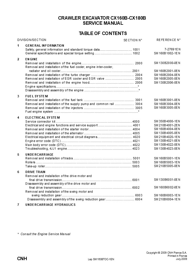
CRAWLER EXCAVATOR CX160B-CX180B SERVICE MANUAL
TABLE OF CONTENTS SECTION N
DIVISION/SECTION
REFERENCE N
- GENERAL INFORMATION
- Safety, general information and standard torque
data..................................... 1001 - General specifications and special torque setting
........................................... 1002 - ENGINE
- Removal and installation of the
engine............................................
................ 2000 Removal and installation
of the fuel cooler, engine inter-cooler, - radiator and oil cooler...........................
..................................................
..... 2001 - Removal and installation of the turbo charger
.................................................
2004 Removal and installation of EGR cooler and
EGR valve ................................. 2005
Removal and installation of the engine
hood..............................................
..... 2006 Engine specifications.................
..................................................
........................... - Disassembly and assembly of the engine
..................................................
............ - FUEL SYSTEM
- Removal and installation of the fuel tank
..................................................
....... 3001 Removal and installation of the
supply pump and common rail ......................
3004 Removal and installation of the injectors
..................................................
....... 3005 Fuel engine system
..................................................
.............................................. - ELECTRICAL SYSTEM
- Service connector kit ............................
..................................................
......... 4000 - Electrical and engine functions and service
support .......................................
4001 - Removal and installation of the starter
motor.............................................
..... 4004 - Removal and installation of the alternator
..................................................
..... 4005 - Electrical equipment and electrical circuit
diagrams........................................
4020 Engine error code (DTC) ....................
..................................................
........... 4021 - Main body error code (DTC)........................
..................................................
.. 4022 - Troubleshooting, 4JJ1 engine......................
..................................................
.. 4023 - UNDERCARRIAGE
7-27691EN SM160B1002-1EN
SM130B2000-0EN
SM160B2001-0EN SM160B2004-0EN SM160B2005-0EN
SM130B2006-0EN
SM160B3001-0EN SM160B3004-0EN SM160B3005-0EN
SM350B4000-1EN SM210B4001-2EN SM160B4004-0EN
SM130B4005-0EN SM210B4020-1EN SM130B4021-0EN
SM130B4022-0EN SM130B4023-0EN
SM160B5001-1EN SM160B5003-1EN SM210B5005-0EN
SM130B6001-0EN
SM160B6002-0EN
SM160B6003-1EN SM210B6004-1EN
Consult the Engine Service Manual
Copyright 2009 CNH France S.A. Printed in
France July 2009
CNH
Lep SM160BTOC-1EN
2
DIVISION/SECTION SECTION N
REFERENCE N
8 UPPERSTRUCTURE HYDRAULICS Depressurising and
decontaminating the hydraulic system, use of
the vacuum pump and bleeding the components
..............................................
8000 Specifications, troubleshooting, checks and
SM160B8000-0EN
hydraulic pressure settings .......................................................................... 8001 Removal and installation of the hydraulic reservoir ......................................... 8002 Removal and installation of the main hydraulic pump...................................... 8003 Removal and installation of the main hydraulic control valve........................... 8004 Removal and installation of the attachment cylinders...................................... 8005 Removal and installation of the hydraulic swivel .............................................. 8006 Removal and installation of the pilot blocs....................................................... 8007 Removal and installation of the swing motor .................................................. 8008 Disassembly and assembly of the main hydraulic pump ................................. 8010 Disassembly and assembly of the main hydraulic control valve ...................... 8011 Disassembly and assembly of the attachment cylinders ................................. 8012 Disassembly and assembly of the hand control levers .................................... 8013 Disassembly and assembly of the foot control levers ...................................... 8014 Disassembly and assembly of the cushion valve............................................. 8016 Removal and installation of the safety valve .................................................... 8017 Hydraulic swivel, disassembly and assembly .................................................. 8018 Disassembly and assembly of the swing motor ............................................... 8019 Hydraulic functions .......................................................................................... 8020 Hydraulic component functions........................................................................ 8030 SM160B8001-1EN SM160B8002-0EN SM160B8003-0EN SM160B8004-0EN SM160B8005-0EN SM160B8006-0EN SM160B8007-1EN SM160B8008-0EN SM160B8010-0EN SM160B8011-0EN SM130B8012-0EN SM130B8013-0EN SM160B8014-1EN SM160B8016-1EN SM130B8017-0EN SM160B8018-0EN SM210B8019-0EN SM160B8020-2EN SM160B8030-1EN
9 UPPERSTRUCTURE Removal and installation of the counterweight ................................................ 9002 SM160B9002-0EN
Removal and installation of the boom, dipper and bucket ............................... 9003 Removal and installation of the seat ................................................................ 9004 Removal and installation of the cab and cab equipment ................................. 9005 Air conditioner functions and troubleshooting .................................................. 9006 Air conditioning unit ......................................................................................... 9007 Air conditioning components............................................................................ 9009 Large size hydraulic schematics ................................................................... Pocket Large size electrical schematics ................................................................... Pocket SM160B9003-0EN SM130B9004-0EN SM130B9005-0EN SM210B9006-3EN SM130B9007-0EN SM160B9009-0EN 87593994B 87594000B
NOTE CNH France S.A. Company reserves the right
to make changes in the specification and design
of the machine without prior notice and without
incurring any obligation to modify units
previously sold. The description of the models
shown in this manual has been made in accordance
with the technical speci- fications known as of
the date of design of this document. All data
given in this manual is subject to production
variations. Dimensions and weights are provided
with approximate values and the machine fitting
shown in the illustrations may not correspond
with standard models. For precise information on
specific machine models and versions, please
contact your CASE dealer. Reproduction or
tranlation, even partial, is prohibited without
written authorization from CNH France SA Company.
Lep SM160BTOC-1EN
Issued 07-09
3
Section 1001
1001
SAFETY, GENERAL INFORMATION AND TORQUE
SPECIFICATIONS
Copyright ? 2006 CNH France S.A. Printed in
France February 2006
CNH
Lep 7-27691EN
4
https//www.ebooklibonline.com Hello dear
friend! Thank you very much for reading. Enter
the link into your browser. The full manual is
available for immediate download. https//www.eb
ooklibonline.com
5
1001-2
TABLE OF CONTENTS GENERAL INFORMATION
..................................................
..................................................
...................................
3 SAFETY..........................................
..................................................
..................................................
....................... 4 STANDARD TORQUE DATA
FOR CAP SCREWS AND NUTS...........................
..................................................
.. 6
WARNING This symbol is used in this manual to
indicate important safety messages. Whenever you
see
! this symbol, carefully read the message that
follows, as there is a risk of serious injury.
Lep 7-27691EN
Issued 02-06
6
1001-3
GENERAL INFORMATION Gears
Cleanning
Clean all metal parts except bearings, in a
suitable cleaning solvent or by steam cleaning.
Do not use caustic soda for steam cleaning.
After cleaning, dry and put oil on all parts.
Clean oil passages with compressed air. Clean
bearings in a suitable cleaning solvent, dry the
bearings completely and put oil on the
bearings. Inspection Check all parts when the
parts are disassembled. Replace all parts that
have wear or damage. Small scoring or grooves
can be removed with a hone or crocus cloth.
Complete a visual inspection for indications of
wear, pitting and the replacement of parts
necessary to prevent early failures. Bearings Chec
k bearings for easy action. If bearings have a
loose fit or rough action replace the bearing.
Wash bearings with a suitable cleaning solvent
and permit
Check all gears for wear and damage. Replace
gears that have wear or damage. Oil seals,
O-rings and gaskets Always install new oil seals,
O-rings and gaskets. Put petroleum jelly on
seals and O-rings. Shafts Check all shafts that
have wear or damage. Check the bearing and oil
seal surfaces of the shafts for damage. Service
parts Always install genuine Case service parts.
When ordering refer to the Parts Catalog for the
correct part number of the genuine Case
replacement items. Failures due to the use of
other than genuine Case replacement parts are
not covered by warranty. Lubrication Only use the
oils and lubricants specified in the Operators
or Service Manuals. Failures due to the use of
non-specified oils and lubricants are not
covered by warranty.
DRY BEARINGS WITH
to air dry. DO NOT COMPRESSED AIR. Needle
bearings
Before you press needle bearings in a bore always
remove any metal protrusions in the bore or edge
of the bore. Before you press bearings into
position put petroleum jelly on the inside and
outside diameter of the bearings.
Lep 7-27691EN
Issued 02-06
7
1001-4
SAFETY
This symbol means ATTENTION! BECOME ALERT! YOUR
SAFETY IS INVOLVED. The message that follows the
! symbol contains important information about
safety. Carefully
read the message. Make sure you fully understand
the causes of possible injury or death.
To prevent injury always follow the Warning,
Caution and Danger notes in this section and
throughout the manual. Put the warning tag shown
below on the key for the keyswitch when
servicing or repairing the machine. One warning
tag is supplied with each machine. Additional
tags Part Number 331-4614 are available from
your service parts supplier .
WARNING Before starting engine, study
Operators Manual safety messages. Read all
safety signs on machine. Clear the area of other
persons. Learn and practice safe use of controls
before operating.
! It is your responsibility to understand and
follow manufacturers instructions on machine
operation, service and to observe pertinent laws
and regulations. Operators and Service Manuals
may be obtained from your Case dealer.
WARNING Read the operators manual to
! familiarize yourself with the correct control
functions.
WARNING If you wear clothing that is too loose
or do not use the correct safety equipment for
your job, you can be injured. Always wear
clothing that will not catch on objects. Extra
safety equipment that can be required includes
hard hat, safety shoes, ear protection, eye or
face protection, heavy gloves and reflector
clothing.
WARNING Operate the machine and
! equipment controls from the seat position
only. Any other method could result in serious
injury.
!
WARNING This is a one man machine, no riders
allowed.
!
WARNING When working in the area of the
! fan belt with the engine running, avoid loose
clothing if possible, and use extreme caution.
WARNING When doing checks and tests
! on the equipment hydraulics, follow the
procedures as they are written. DO NOT change
the procedure.
WARNING When putting the hydraulic cylinders on
this machine through the
! necessary cycles to check operation or to
remove air from a circuit, make sure all people
are out of the way.
Lep 7-27691EN
Issued 02-06
8
1001-5
WARNING When servicing or repairing the
machine, keep the shop floor and operators
WARNING Use insulated gloves or mittens when
working with hot parts.
!
! compartment and steps free of oil, water,
grease, tools, etc. Use an oil absorbing
material and/or shop cloths as required. Use
safe practices at all times.
WARNING Lower all attachments to the
! ground or use stands to safely support the
attachments before you do any maintenance or
service.
WARNING Some components of this
! machine are very heavy. Use suitable lifting
WARNING Pin sized and smaller streams of
hydraulic oil under pressure can penetrate the
skin and result in serious infection. If
hydraulic oil under pressure does penetrate the
skin, seek medical treatment
equipment or additional help as instructed in
this Service Manual.
! immediately. Maintain all hoses and tubes in
WARNING Engine exhaust fumes can cause death.
If it is necessary to start the
good condition. Make sure all connections are
tight. Make a replacement of any tube or hose
that is damaged or thought to be damaged. DO NOT
use your hand to check for leaks, use a piece of
cardboard or wood.
! engine in a closed place, remove the exhaust
fumes from the area with an exhaust pipe
extension. Open the doors and get outside air
into the area.
WARNING When the battery electrolyte is frozen,
the battery can explode if (1), you try to
charge the battery, or (2), you try to jump
WARNING When removing hardened pins such as a
pivot pin, or a hardened shaft, use
! start and run the engine. To prevent the
! a soft head (brass or bronze) hammer or use
battery electrolyte from freezing, try to keep
the battery at full charge. If you do not follow
these instructions, you or others in the area
can be injured.
a driver made from brass or bronze and a steel
head hammer.
WARNING When using a hammer to remove and
install pivot pins or separate
! parts using compressed air or using a
grinder, wear eye protection that completely
encloses the eyes (approved goggles or other
approved eye protectors).
WARNING Use suitable floor (service) jacks or
chain hoist to raise wheels or tracks off the
floor. Always block machine in place with
suitable safety stands.
!
Lep 7-27691EN
Issued 02-06
9
1001-6 STANDARD TORQUE DATA FOR CAP SCREWS AND
NUTS Tightening of cap screws, nuts Tighten
alternately so that tightening torque can be
applied evenly. The numbers in the figure below
indicate the order of tightening.
JS00481A Cap screws which have had Loctite used
(white residue remains after removal) should be
cleaned with loght oil or suitable cleaning
solvent and dried. Apply 2-3 drops of Loctite to
the thread portion of the cap screw and then
tighten. Torque table Tighten cap screws and nuts
according to the table below if there are no
other special instructions.
Cap Screw Name Size (Size) Cap Screw Name Size (Size) Cap Screw Name Size (Size) M6 M8 M10 M12 M14 M16 M18 M20
Cap Screw Spanner mm 10 13 17 19 22 24 27 30
Cap Screw Spanner in. 0.39 0.51 0.67 0.75 0.87 0.95 1.06 1.18
Cap Screw Tightening torque Nm 6.9 19.6 39.2 58.8 98.1 156.9 196.1 294.2
Cap Screw Tightening torque lb-ft 5.1 14.5 28.9 43.4 72.3 115.7 144.6 217
Socket Head Cap Screw Spanner mm 5 6 8 10 12 14 14 17
Socket Head Cap Screw Spanner in. 0.20 0.24 0.32 0.39 0.47 0.55 0.55 0.67
Socket Head Cap Screw Tightening torque Nm 8.8 21.6 42.1 78.5 117.7 176.5 245.2 343.2
Socket Head Cap Screw Tightening torque lb-ft 6.5 15.9 31.1 57.9 86.9 130.2 181 253.2
Lep 7-27691EN
Issued 02-06
10
Section 2000
REMOVAL AND INSTALLATION OF THE ENGINE
2000
Copyright ? 2008 CNH France S.A. Printed in
France March 2008
CNH
Lep SM130B2000-0EN
11
2000-3
REMOVAL AND INSTALLATION OF THE ENGINE ASSEMBLY
Caution
Keep away from fire. Be sure to release hydraulic
pressure before beginning work. The air
conditioner circuit is filled with high-pressure
gas, so there is the danger of gas splaying out
when loosening lines. Do not use open flames and
do not allow sparks near the battery.
Caution
Be sure to stop the engine before beginning
work. Be sure to inspect the wire rope and other
lifting equipment before beginning work. Do not
stand or pass under the suspended load.
- 1 Removal of the engine
- Remove the counterweight.
- (For details, see "Removal and Installation of
Coun- terweight") - Remove the pump.
- (For details, see "Removal and Installation of
Pump") - Disassemble the retaining screws (1) and (2), and
then remove the fan shroud (3).
Lep SM130B2000-0EN
Issued 03-08
12
2000-4
4 Disassemble the retaining screws (1), and
then remove the fan guard (2).
2 1 1 RF11001-007
5 Loosen the hoseband (1), and then remove the
upper hose (2) from the radiator.
1 2
6 Loosen the hoseband (3), and then remove the
lower hose (4) from the radiator.
- Use caps to cover the radiator and hoses and pre-
vent the entry of water, dust or dirt. - Before removing the radiator hoses, completely
drain the coolant.
3
4
- 7 Loosen the adjusting bolts (1) on the pipe,
and then remove the 2 pipes (2) and (3) from the
compressor. - Always remove the low-pressure pipe (2) first.
- Attach caps or plugs to the compressor and pipes
to prevent any entry of water, dust or dirt.
1
3
2
NF11002-008
Lep SM130B2000-0EN
Issued 03-08
13
2000-5
- 8 Loosen the hoseband (1) on the inter cooler,
and then remove the hose (2). - Use caps to cover the pipe and hose and prevent
the entry of water, dust or dirt
2 1 NF11002-009
9 Remove the hosebands (1) in the three
locations.
1 NF11002-010
10Insert inside the breather hose (1) that is
on the outside.
1 NF11002-011
Lep SM130B2000-0EN
Issued 03-08
14
2000-6 11Prepare a waste oil can (1). As the
engine oil hose will be removed, first drain the
engine oil.
1 NF11002-012
- 12Remove the hoses (1).
- Mark the engine and hoses so that the connectors
match at the time of assembly. - Attach caps or plugs to the engine and hoses to
pre- vent any entry of water, dust or dirt. - Clean the engine and hoses by spraying with a
parts cleaner to prevent scratches and prevent
dirt from accumulating on the connectors.
1
NF11002-013
- 13Remove the bolt (1), and then remove the
battery cable (2) on the negative side. - When removing the terminal and harness, secure
them so that do not interfere with the frame. - Also, cover with a rubber cap to protect against
sparks.
2 1 NF11002-014
Lep SM130B2000-0EN
Issued 03-08
15
2000-7
14Remove the nut (1), and then remove the wire
(2) from the starter motor.
1
2
NF11002-015
15Remove the jump-start protector (3), remove
the nut (1), and then remove the wire (2) from
the starter motor.
1 3 2 NF11002-016
- 16Remove the hose stopper (1), and then remove
the fuel hose (2). - Attach caps or plugs to the engine and hoses to
pre- vent any entry of water, dust or dirt.
1 2 NF11002-017
- 17Remove the hose stopper (1), and then remove
the fuel hose (2). - Attach caps or plugs to the engine and hoses to
pre- vent any entry of water, dust or dirt.
NF11002-018
2
1
Lep SM130B2000-0EN
Issued 03-08
16
2000-8 18Disassemble the retaining screws (1),
and then remove the box cover (2).
1 2 NF11002-019
- 19Remove the connectors (1) in the box.
- After tying the connectors together, put them in
a plastic bag.
1 NF11002-020
- 20Loosen the hoseband (1), and then remove the
heater hose (2). - Attach caps or plugs to the engine and hoses to
pre- vent any entry of water, dust or dirt.
1 2 NF11002-021
- 21Loosen the hoseband (1), and then remove the
heater hose (2). - Attach caps or plugs to the engine and hoses to
pre- vent any entry of water, dust or dirt.
1 2 NF11002-022
Lep SM130B2000-0EN
Issued 03-08
17
2000-9
- 22Loosen the hoseband (1), and then remove the
radiator hose (2). - Use caps to cover the line and hose and prevent
the entry of water, dust or dirt.
2 1 NF11002-023
- 23Loosen the hoseband (1), and then remove the
air hose (2). - Use caps to cover the line and hose and prevent
the entry of water, dust or dirt.
2 1 NF11002-024
- 24Loosen the hoseband (1), and then remove the
air hose (2). - Use caps to cover the line and hose and prevent
the entry of water, dust or dirt.
2 1 NF11002-025
25Remove the connector (1) from the alternator.
1 NF11002-026
Lep SM130B2000-0EN
Issued 03-08
18
2000-10 26Remove the nut (1), and then remove
the wires (2) from the alternator.
2 1 NF11002-027
27Remove the bolt (1), and then remove the
breather hose clamp (2).
2 1 NF11002-029
28Connect the 2 shackles (1), and then use the
wires and crane to secure the engine.
1 1 NF11002-030
Lep SM130B2000-0EN
Issued 03-08
19
2000-11
29Disassemble the retaining screws (1) from the
mount.
1
1
1
1
NF11002-031
30Use the wires and crane to lift the engine.
31Thoroughly check that the location is safe
before lowering the engine on wood planks, etc.
NF11002-032
Lep SM130B2000-0EN
Issued 03-08
20
- 2000-12
- 2 Installation of the engine
- To install the engine, perform the reverse of the
removal procedure. - After installing the engine, resupply coolant and
engine oil, perform fuel line air bleeding, and
perform filling for the air conditioner gas. - For details, see the individual explanations for
each procedure. - Run the engine at no-load idling and check for
any water or oil leaks. - Attach the hydraulic pump, covers, and
counterweight. - For details, see the individual explanations for
each procedure.
Lep SM130B2000-0EN
Issued 03-08
21
2001-3
REMOVAL AND INSTALLATION OF FUEL COOLER
Caution
Be sure to stop the engine before beginning
work. As the fuel hose will be removed, strictly
prohibit open flames.
- 1 Removal of fuel cooler
- Mark the fuel cooler and hoses so that the
connec- tors match at the time of assembly. - Loosen the hosebands (3) and (4), and then remove
the hoses (1) and (2).
2 4
- Fuel will spill out, so place a drip pan directly
below the area. - Attach caps or plugs to the fuel cooler and hoses
to prevent any entry of water, dust or dirt.
1
3
NF11002-060
2 Disassemble the retaining screws (1), and
then remove the fuel cooler unit (2).
1 2 NF11002-061
- 2 Installation the fuel cooler
- Perform the reverse of the removal procedure.
- After connecting the hoses, carefully check for
any fuel leaks.
Lep SM160B2001-0EN
Issued 07-09
22
2001-4 REMOVAL AND INSTALLATION OF INTER COOLER
Caution
Be sure to stop the engine before beginning
work. As the fuel hose will be removed, strictly
prohibit open flames.
- 1 Removal of inter cooler
- Remove the fuel cooler.
- (For details, see "Removal and Installation of
Fuel Cooler") - Loosen the bolts (1), and then remove the cover
(2).
2 1 NF11002-066
3 Loosen the hosebands (1) in the two
locations, and then remove the hoses (2).
1 2 NF11002-067
4 Loosen the hosebands (1) in the two
locations, and then remove the hoses (2).
1 2 NF11002-068
Lep SM160B2001-0EN
Issued 07-09
23
2001-5
5 Remove the bolt (1).
1 NF11002-069
6 Attach a wire to the top section of the inter
cooler using a shackle, and lift the inter
cooler to remove it.
NF11002-070
2 Installation of inter cooler Perform the
reverse of the removal procedure. Check for any
air leaks.
Lep SM160B2001-0EN
Issued 07-09
24
2001-6 REMOVAL AND INSTALLATION OF RADIATOR
Caution
Do not remove the radiator cap when the radiator
coolant temperature is high. Hot liquid could
spray out.
Caution
Be sure to release hydraulic pressure before
beginning work. Be sure to stop the engine before
beginning work. Be sure to inspect the wire rope
and other lifting equipment before beginning
work. Do not stand or pass under the suspended
load.
- 1 Removal of radiator
- Disassemble the retaining screws (1), and then
remove the under cover (2).
1 3 2 LM13009-001
2 Place the drain tank (4) under the drain hose
(3).
3 4 LM13009-002
- 3 To make it easier to drain the coolant,
remove the radiator cap (1). - After draining the coolant, install the cap (1).
1 NM13002-003
Lep SM160B2001-0EN
Issued 07-09
25
2001-7
4 Loosen the drain plug (6), and then drain the
cool- ant.
6 LM13009-003
5 Remove the bolts (9), and then remove the
cover (10) and (38).
9
10
38
LM13009-005
- 6 Loosen the hose band (12), and then remove
the upper hose (13) and lower hose (14) from the
radia- tor. - Use caps to cover the radiator and hoses to
prevent the entry of water, dust or dirt.
12 13 14 12 LM13009-007
Hose band tightening torque for hose
installation 4.9 - 5.9 Nm
Lep SM160B2001-0EN
Issued 07-09
26
2001-8 7 Loosen the hoseband (7), and then
remove the hose (8) from the radiator.
7 8 LM13009-004
- Use caps to cover the radiator and hoses and pre-
vent the entry of water, dust or dirt.
Hose band tightening torque for hose
installation 8.8 - 9.8 Nm
8 Remove the 7 bolts (11) from the radiator
cover (39).
11 39 11 LM13009-006
9 Remove the drain plug (15), loosen the hose
band (17), and then remove the hose (16).
1 2 3 NM13002-009
Tightening torque for drain plug installation
14.7 - 24.5 Nm
Lep SM160B2001-0EN
Issued 07-09
27
Suggest If the above button click is invalid.
Please download this document first, and then
click the above link to download the complete
manual. Thank you so much for reading
28
2001-9
- 10Loosen the hose band (19), and then remove
the hose (18) from the radiator cap. - Attach caps or plugs to the hose to prevent any
entry of water, dust or dirt.
18 19 LM13009-008
11Turn up the rubber band (1) on the fan.
1
NM13002-011
Lep SM160B2001-0EN
Issued 07-09
29
https//www.ebooklibonline.com Hello dear
friend! Thank you very much for reading. Enter
the link into your browser. The full manual is
available for immediate download. https//www.eb
ooklibonline.com
Recommended
CrystalGraphics Presentations


