
CASE 580 Super L Loader Backhoe Service Repair Manual Instant Download
Title:
CASE 580 Super L Loader Backhoe Service Repair Manual Instant Download
Description:
CASE 580 Super L Loader Backhoe Service Repair Manual Instant Download –
Number of Views:0
Title: CASE 580 Super L Loader Backhoe Service Repair Manual Instant Download
1
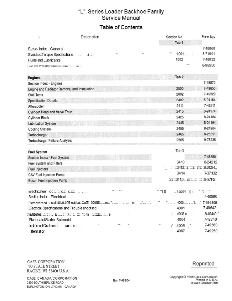
L Series Loader Backhoe Family Service
Manual Table of Contents Description
Form N.o.
)
Section Index - General 7-48860
StandadTorqueSpecifications .i " 1.001 . 8 71601
Fluids and Lubricants 1002 7-48632
Loñtft9 PI0dUCt mChaEtm mm m " " 8-98900
Tab 3 3410 8-24212 3413 i i
m .8-.24234.,, 3414 7-37132 ,i
341,5,.. i.,ii. ... . .8-37142
...
. .Elëctricatee c. c .. . c.c c.cc .. .. ... " " " " "'t tt " "'t tt " "'t tt ..Tabt4 ))i ..Tabt4 ))i )
Section Index - Electrical 7-48890
Removaland tnstallätioûôf ElectricalCatTÏ 0I2ëf\tS. ee Electrical Specifications and Troubleshooting Removaland tnstallätioûôf ElectricalCatTÏ 0I2ëf\tS. ee Electrical Specifications and Troubleshooting .. .. .. e. .. e. ..... . .. " 4000... . .. i 4001 7-49430tî 7-48642 7-49430tî 7-48642
mBättërfes. .. ... e. ..... / . im . .c.e.... ....e . .c.e.... ....e . .c.e.... ....e . .c.e.... ....e . .c.e.... ....e .é0ö3 m .é0ö3 m ....8-49440..
Starter and Starter Solenoid 4004 4004 7-48740
. Instrùment.Clustermi i c.m.m .....m....... "" " " 4005 ., 7-49560 7-49560
lternator 4007 7-49250 7-49250
CASE CORPORATION 700 STATE STREET RACINE. WI
534Ot U.S.A.
Reprinted
Copyright Ô 1996 Case Corporation Printed in
U.S.A. lssued October1996
CASE CANADA CORPORATION 3350 SOUTH SERVICE ROAD
BURLINGTON, ON L7N 3M6 CANADA
Bur 7-48854
2
L Series Loader Backhoe Family Service
Manual Table of Contents Description
Section No.
F0rm No.
7-48902
Se"ct.ion Ind""ex - Steering
mt. ............"
" 50.01 im. 5002 e i500.3 e
. 5005
7-49000 7-4946 iii7-494
0 7-48770 5006 . .. . 7-49570 5006 7-51060
580S/Jpef L and"590S petmL-
Stèëring.Sp4cïtications,Presstfe Chëcks and/
Front Axle - Two Wheel Drive Front
Axle-FourWheelDrive- 580Land
580SuperL Front Axle - Four Wheel Drive -
590 Super L
Tab 6
Power Train Section Ïndex-mPöwër/Trairtm.e.
. .. Removal and Installation ot Power
Train Components TransrotSsion Specifications.Pre
ssuCrehecks and Troubieshoottng ." Wheels and
Tires
. " 7-4"8912 7-49580 7-48660 7-49590
6000 . 6002... .. 6003 ... .. fiO04
6004 600.7 . . 7-48790
" "
" . ... 7"-48780. 7-51130
..Rear Axlemand.PIanetanesi-5B0L
and580mSuper .
..7Q00..........,,............et
..7'.4.9öO0
7-49490
7003
Master Cylinder
Tab8 "" . ../.,.7-4B933 8001 7-49630
Remova"l and Installation of Hydraulic
Components
. m.. .. .m..... 7-490.1. 1
580L-mHydraulIcSpecifcations,Troubleshootirtg
m, andPressureChecks m mmm mmi m
.i m
. . .
Troubleshoot.ing, and
580 Super L and 590 Super L Hydraulic
Specifications, Pressure Checks
7-48672
8002
80ü3 ./.ee 7-49640i 8004
7-49170
i
Hydraulic Pump - 580L S' L and 590.S'peL
i i..i Lodder Con rol Valv0
"
. "" " .. 8004 .. .. .. . ? 49.180
8005 7-49191
".. 8006 7-49200
8007 7-50760
I /ylaifIleI5 I ï.ïï.ï.ï.I'.,.ï'..... ""
Backhoe Control Valve - 580L Baúkhoe
ControlmVaIvé- 580Super L and 590 Super
L. Auxiliary Control Valve
8"007 8008 ii8O09 .mi 8010
. . 7-49210
7-51670
....
i . " 7-52. e 7-52460
lssued 10-96
Printed in U.S.A.
Bur 7-48854
3
L Series Loader Backhoe Family Service
Manual Table of Contents Description îîî. î. ..
îî. t..î î. î.î..î.îî.î...t. t. . .îî.....î. "
" " " " "" " " "
Section No. . îî.t.î. î. î.it.î.îîîTgb.9 t.
Form No. " "
.îî. OÏ.ÊÏtÊ Î E jIi fÎÎËTît îî î
Section Index - Mounted Equipment Section Index - Mounted Equipment Section Index - Mounted Equipment Section Index - Mounted Equipment 7-48942 7-48942
Pèdals ànd Levër4 .. e e ... me. t e . m m "e t Pèdals ànd Levër4 .. e e ... me. t e . m m "e t Pèdals ànd Levër4 .. e e ... me. t e . m m "e t Pèdals ànd Levër4 .. e e ... me. t e . m m "e t . .t mm. m e m e 9ôô1 . .t mm. m e m e 9ôô1 . .t mm. m e m e 9ôô1 . .t mm. m e m e 9ôô1 . .t mm. m e m e 9ôô1 7-.48680 7-.48680
Air Conditioning Troubleshooting For Systems With R-134a Refrigerant Air Conditioning Troubleshooting For Systems With R-134a Refrigerant Air Conditioning Troubleshooting For Systems With R-134a Refrigerant Air Conditioning Troubleshooting For Systems With R-134a Refrigerant 9002 9002 9002 9002 9002 7-50091 7-50091
A.ir Conditionin.9tS.y.s.t.e....n....G. t...au.....9.e.s..a...n....d.t..Tes.t..in.Û.FD.r...S...Ys..tettr.i..s. W... ith.R..-1.3..4....a.. Ref..r.iÜ.erant A.ir Conditionin.9tS.y.s.t.e....n....G. t...au.....9.e.s..a...n....d.t..Tes.t..in.Û.FD.r...S...Ys..tettr.i..s. W... ith.R..-1.3..4....a.. Ref..r.iÜ.erant A.ir Conditionin.9tS.y.s.t.e....n....G. t...au.....9.e.s..a...n....d.t..Tes.t..in.Û.FD.r...S...Ys..tettr.i..s. W... ith.R..-1.3..4....a.. Ref..r.iÜ.erant A.ir Conditionin.9tS.y.s.t.e....n....G. t...au.....9.e.s..a...n....d.t..Tes.t..in.Û.FD.r...S...Ys..tettr.i..s. W... ith.R..-1.3..4....a.. Ref..r.iÜ.erant A.ir Conditionin.9tS.y.s.t.e....n....G. t...au.....9.e.s..a...n....d.t..Tes.t..in.Û.FD.r...S...Ys..tettr.i..s. W... ith.R..-1.3..4....a.. Ref..r.iÜ.erant A.ir Conditionin.9tS.y.s.t.e....n....G. t...au.....9.e.s..a...n....d.t..Tes.t..in.Û.FD.r...S...Ys..tettr.i..s. W... ith.R..-1.3..4....a.. Ref..r.iÜ.erant A.ir Conditionin.9tS.y.s.t.e....n....G. t...au.....9.e.s..a...n....d.t..Tes.t..in.Û.FD.r...S...Ys..tettr.i..s. W... ith.R..-1.3..4....a.. Ref..r.iÜ.erant A.ir Conditionin.9tS.y.s.t.e....n....G. t...au.....9.e.s..a...n....d.t..Tes.t..in.Û.FD.r...S...Ys..tettr.i..s. W... ith.R..-1.3..4....a.. Ref..r.iÜ.erant 90ô3 7-50901 7-50901
Air Conditioning System Service For Systems With R-134a Refrigerant Air Conditioning System Service For Systems With R-134a Refrigerant Air Conditioning System Service For Systems With R-134a Refrigerant Air Conditioning System Service For Systems With R-134a Refrigerant Air Conditioning System Service For Systems With R-134a Refrigerant Air Conditioning System Service For Systems With R-134a Refrigerant Air Conditioning System Service For Systems With R-134a Refrigerant Air Conditioning System Service For Systems With R-134a Refrigerant 9004 7-51030 7-51030
Air Conditioning Components ServiceFôrSystemsWithR-t04a Refrigerant. ... m...i. ...i. i Air Conditioning Components ServiceFôrSystemsWithR-t04a Refrigerant. ... m...i. ...i. i Air Conditioning Components ServiceFôrSystemsWithR-t04a Refrigerant. ... m...i. ...i. i Air Conditioning Components ServiceFôrSystemsWithR-t04a Refrigerant. ... m...i. ...i. i Air Conditioning Components ServiceFôrSystemsWithR-t04a Refrigerant. ... m...i. ...i. i Air Conditioning Components ServiceFôrSystemsWithR-t04a Refrigerant. ... m...i. ...i. i Air Conditioning Components ServiceFôrSystemsWithR-t04a Refrigerant. ... m...i. ...i. i Air Conditioning Components ServiceFôrSystemsWithR-t04a Refrigerant. ... m...i. ...i. i 9005i i i m7-5i1050m i m7-5i1050m
Loader Loader Loader Loader Loader Loader Loader Loader 9006 7-49510 7-49510
ROPS Ca6"and CanoP"C mm." " " " " "" 9007 9007 7-49520
Backhoe 9008 9008 7-49530
SeatmandSeat.Belts. .i.. ... . i... i i " "" 9009m m 9009m m 7-.49540
-T n" -"" ""d.,El" -" " . - "
.
ydraulic an . ectrical. Schematic Foldout(580L)
Hydraulic and Electrical Schematic Foldout (580
Super L and 590 Super L)
Bur 7-48854
Issued 10-96
Printed in U.S.A.
4
https//www.ebooklibonline.com Hello dear
friend! Thank you very much for reading. Enter
the link into your browser. The full manual is
available for immediate download. https//www.ebo
oklibonline.com
5
Section 102
FLUIDS AND LUBRICANTS
CASE CORPORATION 700 STATE STREET RACINE, WI
534Ot U.S.A
CASE CANADA CORPORATION 3350 SOUTH SERVICE ROAD
BURLINGTON, ON L7N 3M6 CANADA
Copyright O 1996 Case Corporation Printed in
U.S.A. Issued October, 1996
Bur 7-48632
6
1002-3
CAPACITIES AND LUBRICANTS Engine Oil Capacity
with Filter Change ...............................
..................................................
............................... 11.6 U.S. quarts
(11 litres) Type of oil ..........................
..................................................
.................................. See Engine Oil
Recommendations on page 4 Engine Cooling
System Capacity without heater ...................
..................................................
..............................................
16.7 U.S. quarts (15.8 litres) Capacity with
heater ...........................................
..................................................
............................17.4 U.S. quarts
(16.5 litres) Type of coolant ....................
...............................................
Ethylene glycol and water mixed for the lowest
ambient temperature At least 50/50 mix Fuel
Tank Capacity ....................................
..................................................
..................................................
.. 31.4 U.S. gallons (123 litres) Type of fuel
..................................................
..................................................
............... See diesel fuel specifications on
page 5 Hydraulic System Hydraulic reservoir
refill capacity with filter change
..................................................
....................... 14.4 U.S. gallons (54.5
litres) Hydraulic reservoir refill capacity
without filter change ............................
........................................ 13.9
U.S. gallons (52.6 litres) Type of oil
..................................................
..................................................
..................................................
..... Case TCH Fluid Transmission 2 Wheel
Drive Total System ...............................
..................................................
..............................................
19.5 U.S. quarts (18.5 litres) Refill with or
without filter ...................................
..................................................
...........................16.9 U.S. quarts (16
litres) Type of oil ..............................
..................................................
................................................
Case Hy Tran Plus (MS1207) 4 Wheel Drive Total
System ...........................................
..................................................
.........................................22 U.S.
quarts (21 litres) Refill with or without filter
..................................................
..................................................
......... 19.5 U.S. quarts (18.5 litres) Type of
oil ..............................................
..................................................
................................ Case Hy Tran
Plus (MS1207) Front Axle - Four Wheel Drive -
580L and 580 Super L Capacity of center bowl
..................................................
..................................................
................... 5.8 U.S. quarts (5.5
litres) Capacity of planetary (each)
..................................................
..................................................
.............0.75U.S. quart (0.7 litres) Type of
oil ..............................................
..................................................
................... Case Wet Brake Lubricant (MS
1317) Front Axle - Four Wheel Drive - 590 Super
L Capacity of center bowl ........................
..................................................
............................................. 6.9
U.S. quarts (6.5 litres) Capacity of planetary
(each) ...........................................
..................................................
.................. 1.05 U.S. quarts (1.0
litres) Type of oil ..............................
..................................................
................................... Case Wet
Brake Lubricant (MS 1317) Rear Axle - 580L and
580 Super L Capacity of center bowl
..................................................
..................................................
.................. 15 U.S. quarts (14.2
litres) Capacity of planetary (each)
..................................................
..................................................
.............1.6 U.S. quarts (1.5 litres) Type of
oil - Axle No. 114367A2 and 114367A3..............
..............................................
Case Wet Brake Lubricant (MS 1317) Type of oil -
Axle No. 114367A4 and After.......................
..................................................
........ Case Hy-Tran Plus (MS 1207 Rear Axle -
590 Super L Capacity of center bowl
..................................................
..................................................
.................. 15 U.S. quarts (14.2
litres) Capacity of planetary (each)
..................................................
..................................................
........... 2.1 U.S. quarts (2.00 litres) Type of
oil - Axle No. 127599A2...........................
..................................................
....... Case Wet Brake Lubricant(MS 1317) Type of
oil - Axle No. 127599A3 and After.................
..................................................
.............. Case Hy-Tran Plus (MS 1207 Brake
Reservoir ........................................
..................................................
....... (Gets fluid automatically from the
hydraulic system) Conversion Formulas Imperial
quart litres x 0.879877 Imperial gallon
litres x 0.219969
Bur 7-48632
Revised 10-96
Printed in U.S.A.
7
1002-4
ENGINE OIL RECOMMENDATIONS Case IH No.1 Engine
Oil is recommended for use in your Case IH
Engine. Case IH No.1 Engine Oil will lubricate
your engine correctly under all operating
conditions. If Case IH No. 1 Multi-Viscosity
Engine Oil is not available, Case IH No. 1 Single
Grade Engine Oil can be used.
If Case IH No.1 Multi-Viscosity or Single Grade
Engine Oil is not available, use only oil meeting
API engine oil service category CE.
- SAE 1OW-30
654L9
See the chart below for recommended viscosity at
ambient air temperature ranges. NOTE Do not put
Performance Additives or other oil additive
products in the engine crankcase. 7/?e oil
intervals given in thls frlahUal are according to
tests with Case IH lubricants.
AMBIENT AIR TEMPERATURE RANGES Temperature
Fahrenheit 0 10 20 30 40 50 60 70 80
30
20
10
90 100
110
120
MULTI-GRADE OIL
SINGLE GRADE OIL
16 21 27 32 38 43 49
4 10 Temperature Celsius
34
29O
23
18
12 7
Revised 10-96
Printed in U.S.A.
Bur 7-48632
8
1002-5
DIESEL FUEL
Fuel Storage If you keep fuel in storage for a
period of time, you can get foreign material or
water in the fuel storage tank. Many engine
problems are caused by water in the fuel.
Use No. 2 diesel fuel in the engine of this
machine. The use of other fuels can cause the
loss of engine power and high fuel consumption.
In very cold temperatures, a mixture of No. 1 and
No. 2 diesel fuels is temporarily permitted. See
the following Note.
Keep the fuel storage tank outside and keep the
fuel as cool as possible. Remove water from the
storage container at regular periods of time.
NOTE See your fuel dealer for winter fuel
requirements in your area. If the temperature of
the luel is below the cloud point (max appearance
point), wax crystals in the fuel will ca/se the
enpine to lose power or not start.
The diesel fuel used in this machine must meet
the specifications in the chart below or
Specification D975-81 of the American Society for
Testing and Materials. Specifications for
Acceptable No. 2 Diesel Fuel API gravity, minimum
..................................................
..................................................
..................................................
... ........ 34 Flash Point, Minimum
..................................................
..................................................
............................................ 140
F (60 C) Cloud point (wax appearance point),
maximum ..........................................
................................ 5 F (20 C)
See Note above Pour point, maximum
..................................................
..................................................
........ 15 F (26 C) See Note
above Viscosity, at 100 F (88 C) Centistokes
..................................................
..................................................
..................................................
................. 2.0 to 4.3 Saybolt Seconds
Universal ........................................
..................................................
..................................................
...... 32 to 40
Bur 7-48632
Revised 10-96
Printed in U.S.A.
9
SECTION INDEX - ENGINES Section Title Section
Number Engine and Radiator Removal and
Installation .....................................
..................................................
...................... 2000 StallTests............
..................................................
..................................................
..............................................2002
Specification Details...........................
..................................................
..................................................
.................. 2402 Aftercooler
..................................................
..................................................
..................................................
......................... 2411 Cylinder Head and
Valve Train.......................................
..................................................
..........................................
2415 Cylinder Block..............................
..................................................
..................................................
....................... 2425 Lubrication System
..................................................
..................................................
..............................................
2445 Cooling System ..............................
..................................................
..................................................
..................... 2455 Turbocharger
..................................................
..................................................
..................................................
.... 2465 Turbocharger Failure Analysis
..................................................
..................................................
............................... 2565
CASE CORPORATION 700 STATE STREET RACINE, WI
53404 U.S.A.
Copyright O 1995 Case Corporation Printed in
U.S.A. Issued May 1995
CASE CANADA CORPORATION 3350 SOUTH SERVICE ROAD
BURLINGTON, ON L7N 3M6 CANADA
Bur 7-48870
10
Section 20
ENGINE AND RADIATOR REMOVAL AND INSTALLATION
CASE CORPORATION 700 STATE STREET RACINE, WI
53404 U.S.A. CASE CANADA CORPORATION 3350 SOUTH
SERVICE ROAD BURLINGTON, ON L7N 3M6 CANADA
Copyright O 1995 Case Corporation Printed in
U.S.A. Issued May 1995
Bur 7-49650
11
2000-3
RADIATOR REMOVAL
Put identification tags on all disconnected hoses
and wires. Close disconnected hoses and fittings
with caps and plug
STEP 4
STEP 1
BP9502286 Have another person help with the
following procedure. A. Open the hood.
B. Remove the retainers from the hood struts (1)
and disconnect the hood struts from the stud.
Park the machine on a level surface. Raise the
loader and lock the support strut (1) to hold the
loader.
C. Hold the hood in place and disconnect the hood
cable from the radiator shroud on the other side
of the machine.
STEP 2
D. Carefully lower the hood back to the
closed position. STEP 5
Remove the caps screws (1), upper (2) and lower
bumpers (3), and the grille (4) from the front of
the machine.
STEP 3 Remove the bolts, washers, and nuts from
the pivot point on the hood.
Drive the pivot tubes out of the hood pivot
point. Remove the hood from the machine.
Issued 5-95
Printed in U.S.A.
Bur 7-49650
12
2000-4 STEP 6
STEP 8
Slowly remove the radiator cap. Install a hose on
the drain valve and drain the radiator into a
clean container that holds approximately 18 U.S.
quarts (17 litres).
Loosen the clamp (1) and disconnect the lower
radiator hose.
STEP 9
NOTE During installation, fill the radiator and
coo/ant reservoir completely. See Section 1002
for coo/ant specifications. Start and run the
engine until the coolant is at operating
temperature. Stop I/ie engine and c/neck for
leakage. When the coo/ant is cold, c/iec/r the
coolant reservoir level. Add coo/ant as
required. STEP 7
Remove the bolts (1), spacers, washers, and
coolant reservoir from the machine. STEP 10
Disconnect the overflow hose (1) from the
radiator neck. Loosen the clamp and disconnect
the upper radiator hose (2).
Remove the hardware from the fan shroud. Move the
fan shroud away from the radiator.
Issued 5-95
Printed in U.S.A.
Bur 7-49650
13
2000-5
STEP 11
STEP 12
Remove the cap screws (1) and pump guard (2) from
the machine.
Use a sharp knife and cut the warning decal (1).
Remove the cap screws that fasten the lower
brackets(2) to the radiator. Remove the hardware
and the lower brackets (2) from the radiator
shroud. Remove the cap screws and flat washers
that fasten the upper bracket (3) to the
radiator. Remove the cap screws and flat
washers (4) that fastens the condenser if
equipped and oil cooler to the radiator. Litt the
radiator straight up and remove the radiator from
the machine NOTE Installation at t/?e radiator
is the reverse of removal.
Issued 5-95
Printed in U.S.A.
Bur 7-49650
14
2000-6
ENGINE REMOVAL
Put identification tags on all disconnected hoses
and wires. Close disconnected hoses and fittings
with caps and pugs.
STEP 4
STEP 1
BP9502286 Have another person help with the
following procedure. E. Open the hood.
F. Remove the retainers from the hood struts (1)
and disconnect the hood struts from the stud.
Park the machine on a level surface. Raise the
loader and lock the support strut to hold the
loader.
G. Hold the hood in place and disconnect the hood
cable from the radiator shroud on the other side
of the machine.
STEP 2
H. Carefully lower the hood back to the
closed position. STEP 5
Remove the caps screws (1), upper (2) and lower
bumpers (3), and the grille (4) from the front of
the machine.
STEP 3 Remove the bolts, washers, and nuts from
the pivot point on the hood.
Drive the pivot tubes out of the hood pivot
point. Remove the hood from the machine.
Issued 5-95
Printed in U.S.A.
Bur 7-49650
15
2000-7
STEP 6
STEP 8
Loosen the clamp (1) and disconnect the lower
radiator hose.
Slowly remove the radiator cap. Install a hose on
the drain valve and drain the radiator into a
clean container that holds approximately 18 U.S.
quarts (17 litres).
STEP 9
NOTE During installation, fill the radiator and
coolant reservoir completely with coolant. See
Section 1002 tar coolant specifications. Slam and
run the engine until the coolant is at operating
temperature. Stop the engine and check tar
leakage. then the coolant is cold, check the
coolant reservoir level. Add coo/am as
required. STEP 7
Remove the bolts (1), spacers, washers, and
coolant reservoir from the machine. STEP 10
Disconnect the overflow hose (1) from the
radiator neck. Loosen the clamp and disconnect
the upper radiator hose (2).
Remove the hardware from the fan shroud. Move the
fan shroud away from the radiator.
Issued 5-95
Printed in U.S.A.
Bur 7-49650
16
2000-8 STEP 11
STEP 13
Remove the cap screws (1) and pump guard (2) from
the machine.
Disconnect the hoses from the oil cooler.
STEP 14
NOTE If the machine is equipped with air
conditioning and a battle plate with a slot for
the drier hose, go to step 21. If the mach/ne is
equipped with air conditioning and a baffle plate
with out a slot for the drier hose, do steps 17
through 19 to keep from discharging the air
conditioning system. For machines without air
conditioning, do steps 12 through 16.
STEP 12
Remove the studs (1). Remove the bolts (2) and
nuts that fasten the radiator shroud to the
frame. STEP 15 Remove the radiator shroud,
radiator, and oil cooler as an assembly.
STEP 16 Go to step 31.
Loosen and remove the cap screws, flat washers,
and if equipped, lock washers that fasten the
baffle plate to the front of the machine.
NOTE Do s/eps 17 through 19 lor machine with air
conditioning and a balfle plate without a
slot. STEP 17 Remove all straps that hold the
hose for the air conditioning system drier from
the front of the machine back to the cab. It is
important to have as much hose as possible at the
front of the machine to do the next step.
Bur 7-49650
Issued 5-95
Printed in U.S.A.
17
2000-9
STEP 18 Loosen and remove the cap screws, flat
washers, and if equipped, lock washers that
fasten the baffle plate to the front of the
machine.
STEP 23
STEP 19 Move the baffle plate and drier for
access to the hoses on the left side of the oil
cooler. STEP 20 Go to Step 24.
Put a block under the oil cooler to hold the
radiator, oil cooler, and condenser in place when
the radiator shroud is removed.
NOTE Do steps 21 and 22 lor machines with air
conditioning and a battle plate with a slot.
STEP 24
STEP 21
Use a sharp knife and cut the warning decal (1).
Remove the cap screws that fasten the lower
brackets(2) to the radiator. Remove the hardware
and the lower brackets (2) from the radiator
shroud. Remove the cap screws and flat washers
that fasten the upper buckets(3) to the radiator.
Remove the self-locking nut and clamp from the
drier.
STEP 22
STEP 25
Remove the cap screws, flat washers, and if
equipped, lock washers that fasten the baffle
plate to the front of the machine. Remove the
baffle plate from the drier and the machine.
Remove the studs (1) from the frame. Remove the
bolts and nuts (2) that fasten the radiator
shroud to the frame.
NOTE Do the remaining steps lor all machines.
Bur 7-49650
Issued 5-95
Printed in U.S.A.
18
2000-10 STEP 26 Remove the radiator shroud from
the radiator, oil cooler, and condenser.
STEP 30
STEP 27
Pull the foam baffle away from the
condenser. STEP 31
Disconnect the electrical connector for the
drier. STEP 28
For machines with a slot in the baste plate, move
the condenser and drier assembly out of the way
as shown. For machines without a slot in the
baffle plate, have another person help to move
the condenser, baffle plate, and drier assembly
away from the radiator and oil cooler assembly
and fasten the assembly out of the way.
Disconnect the hoses from the oil cooler on both
sides of the oil cooler.
STEP 32
STEP 29
Remove the radiator and oil cooler. Remove the
fan shroud (1) from the fan. Remove the cap
screws and flat washers that fasten the condenser
and oil cooler to the radiator.
Printed in U.S.A.
Bur 7-49650
Issued 5-95
19
2000-11
STEP 33
STEP 36
Disconnect the hoses (1) from the LH side of the
pump. Remove the bolts and lock washers that
fasten the flange (2) on the RH side of the pump.
Remove the hardware that fastens the compressor
to the bracket.
STEP 37
STEP 34
Remove the belt and lay the compressor over the
side of the flame
Loosen and remove the cap screws that fasten the
pump to the pump mounting bracket.
NOTE During installation, adjust the drive belt a
ccording he instructions in Section 9003.
NOTE Oo steps 35 through 37 tar rnachlnes with
air conditioning.
STEP 38
STEP 35
Remove the battery cover from the right step. If
the machine has only one battery, disconnect the
negative battery cable from the battery.
Disconnect the electrical connector (1). Remove
the tie strap (2). Remove the hardware (3) from
the adjusting straps
Printed in U.S.A.
Issued 5-95
Bur 7-49650
20
2000-12 STEP 39
STEP 42
If the machine has two batteries, remove the
terminal nut. Remove the negative battery cable
from the terminal and move the negative battery
cable away from the battery. Make sure the jumper
cable is installed on the terminal and start the
terminal nut onto the terminal.
Remove the cap screws and flat washers that
fasten the cover to uprights. Remove the cover
and air cleaner as an assembly.
STEP 43
STEP 40
If the machine has ether injection, remove the
tie straps (1) and sleeve (2) from the tube (3)
and wire (4). Disconnect the tube (3) and the
wire (4).
Loosen the clamp for the exhaust pipe at the
muffles. Remove the exhaust pipe from the muftler.
STEP 44
STEP 41
Disconnect the throttle rod (1). Disconnect the
wiring clamp (2). Disconnect the wire from the
oil pressure sender (3). Disconnect the fuel
shutoff wire (4).
Remove the tie strap (1). Disconnect the
electrical connectors (2) for the air restriction
indicator. Loosen the clamp (3) on the air
cleaner hose. Disconnect the hose from the air
cleaner. Bur 7-49650
Printed in U.S.A.
Issued 5-95
21
2000-13
STEP 48
STEP 45
BP95023t
Remove the harness clamps (1). Disconnect the
wires (2) from the alternator.
Disconnect the fuel lines (1) and (2).
STEP 46
STEP 49
Disconnect the heater hose (1).
Loosen the clamp and disconnect the heater hose.
STEP 47
STEP 50
Disconnect the coolant temperature sender (1) and
coolant temperature switch (2).
Disconnect the ground strap (1). Disconnect the
wires (2) from the starter.
Issued 5-95
Printed in U.S.A.
Bur 7-49650
22
2000-14 STEP 51
STEP 54
950 310 Remove the bolts, flat washers, and nuts
from the front engine mount.
Install the CAS-1690 tool to turn the flywheel
for access to the cap screws.
NOTE During installation, tighten the
self-locklng nuts to 360 to 420 pound-lnches (41
fa 47 Non).
STEP 55
STEP 52
Loosen and remove all six cap screws and lock
washers that fasten the torque converter to the
flywheel.
Connect lifting equipment to the lifting eyes on
the engine to hold the engine in place.
NOTE Be careful during installation when
installing the cap screws and lock washers that
tasien the torque converter to the flywheel.
Tighten the cap screws to 38 to 42 pound-leet (52
to 57 Nm).
NOTE There are six cap screws with lock washers
that /asten the torque converter to the flywheel.
the engine nust be rotated to align each cap
scren' with f/ie access hole in the flywheel
housing at the ie/f side at/he engine.
STEP 56 Loosen and remove the 12 cap screws and
flat washers that fasten the transmission to the
engine. Move the heater hose and clamps out of
the way.
STEP 53 Remove the plastic plug from the flywheel
housing. Remove the hose from the bracket and
remove the cover and gasket from the access hole
for the cap screws
Issued 5-95
Printed in U.S.A.
Bur 7-49650
23
2000-15
- STEP 57
- Move the engine forward and raise the engine.
Remove the engine from the machine. - NOTE Installation at ihe engine is the reverse
of removal. Before starling the enpine, do the
following - The turbocharger must be filled with oil.
Disconnect the wire from the fuel shutoff
solenoid. Actuate the starter for 10 to 20
seconds to fill the turbocharger with oil.
Connect the wire to the fuel shutoff solenoid. - The hydraulic pump must be filled with oil. Do
the following procedure to fill the hydraulic
pump with oil - Make sure the oil level in the hydraulic
reservoir is correct. - Remove the cap from the hydraulic reservoir.
- Use a nozzle and shop air to pressurize the
hydraulic reservoir. Wrap a shop cloth around the
end of the hose at the nozzle. - NOTE 5 psi (34.5 kPa) to 10 psi (69.0 kPa) is
all that is required to move the oil. Pressure
above 10 psi (69.0 kPa) can dhi!9 the
hydraulic reservoir. - Have another person start and run the engine at
low idle while shop air is being applied to the
hydraulic reservoir.
Issued 5-95
Printed in U.S.A.
Bur 7-49650
24
2000-16
B9503081T
- Radiator
- Fan Shroud
- Coolant Recovery Bottle
- Ball/e
- Oil Oooler
- Air Conditioning Condenser
Radiator Installation
Bur 7-49650
Issued 5-95
Printed in U.S.A.
25
Suggest If the above button click is invalid.
Please download this document first, and then
click the above link to download the complete
manual. Thank you so much for reading
26
2000-17
6
B9503082T
S. Cap Screw 6. Flat Washer, Special
- Grommet
- Spacer
- Radiator Shroud
- Bolt, Radiator Shroud to Chassis Frame
- Nut
- Bracket, Radiator Shroud to Radiator
Radiator Shroud
Bur 7-49650
Issued 5-95
Printed in U.S.A.
27
https//www.ebooklibonline.com Hello dear
friend! Thank you very much for reading. Enter
the link into your browser. The full manual is
available for immediate download. https//www.ebo
oklibonline.com
Recommended
CrystalGraphics Presentations


