
CASE IH 7210 Tractor Service Repair Manual Instant Download 3
Title:
CASE IH 7210 Tractor Service Repair Manual Instant Download 3
Description:
CASE IH 7210 Tractor Service Repair Manual Instant Download 3 –
Number of Views:0
Title: CASE IH 7210 Tractor Service Repair Manual Instant Download 3
1
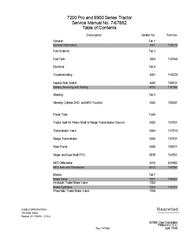
7200 Pro and 8900 Series Tractor Service Manual
No. 7-67882 Table of Contents Description
Section No. Tab 1
Form No.
General
Fuel Systems
Tab 3
Fuel Tank
3004
7-87440
Electrical
Tab 4
Troubleshooting
4001
7-66720
Neutral Start Switch
4005
7-85531
Steering
Tab 5
Steering Cylinder-2WD and MFD Tractors
5002
7-85291
Power Train
Tab6
Tractor Split for Pinion Shaft or Range
Transmission Service
6002
7-67501
Transmission Valve
6004
7-67510
Range Transmission
6006
7-67531
Rear Frame
6008
7-85671
6010
Single and Dual Shaft PTO
7-67551
MFD Differential
6012
8-91962
Brakes
Tab 7
Hydraulic Trailer Brake Valve
7002
Pneumatic Trailer Brake Valve
7004
Reprinted
CASE CORPORATION 700 State Street Racine, WI
53404 U.S.A.
Oc 1998 Case Corporation Printed in U.S.A. April,
1998
Rac 7-67882
2
Description
Section No.
Form No.
Hydraulics Hydraulic Troubleshooting Tab 8 8001 7-66710
Electrical PTO Valve 8003 7-65430
Hydraulic Filters 8005 7-60782
Charge/Lube Dual Gear Pump 8007 7-87460
Electronic Hitch Calibration and Error Codes 8009 7-67870
Hitch Valve 8011 7-68761
Chassis Tab 9
Air Conditioner System Service 9002 7-67241
Air Conditioning Components 9004 7-67260
Tractor Seat 9006 7-87730
8900 Decal Locations 9008 7-87750
Pedal and Lever Adjustment 9010 7-87770
Printed in U.S.A.
April, 1998
Rac 7-67882
3
Section 1001
GENERAL INFORMATION 7200 Pro and 8900 Series
Tractors
CASE CORPORATION 700 State Street Racine, WI
53404 U.S.A.
CASE CANADA CORPORATION 450 Sherman
Avenue Hamilton, ON L8N 4C4 CANADA
_at_ 1998 Case Corporation Printed in U.S.A. March,
1998
Rac 7-85710
4
https//www.ebooklibonline.com Hello dear
friend! Thank you very much for reading. Enter
the link into your browser. The full manual is
available for immediate download. https//www.ebo
oklibonline.com
5
1001-3
CONVERSION FACTORS U.S. Customary to SI (Metric)
Units Multiply By To Obtain
SI (Metric) Units to U.S. Customary
Area
square foot (ft2) acre
0.092 903 0.404 686
square meter (m2) hectar (ha)
Force
ounce force (ozf) pound force (16f)
0.278 014 4.448 222
newton (N) newton (N)
Length
inch (in) foot (ft) mile
25.4 0.304 8 1.609 344
millimetre (mm) meter (m) kilometer (km)
kilogram (kg)
Mass
pound (lb)
0.453 592
Mass/Area
ton/acre
2241.702
kilogram per hectare (kg/ha)
Mass/Energy (Fuel Consumption)
pound per brake horsepower- hour (lb/bhp-h)
608.277 4
gram per kilowatt hour (g/kwh)
Mass/Volume (Density)
pound per cubic yard (lb/yd3) 0.593276
0.593 276
kilogram per cubic meter (kg/m)
kilowatt (kw)
Power
horsepower - U.S. customary (hp - U.S. customary)
0.745 700
Pressure
pound per square inch (psi)
6.894 757
kilopascal (kPa)
Temperature
degrees Fahrenheit ('F)
TC5/9 (TF-32)
degree celsius ('C)
newton meter (Nm) newton meter (Nm)
Torque
pound inch (lb in) pound foot (lb ft)
0.112 985 1.355 818
Velocity (Speed)
miles per hour (mph)
1.609 344
kilometer per hour (km/h)
Volume
cubic inch (in3) cubic foot (ft3) cubic yard
(yd) ounce-U.S. fluid (oz) quart-U.S. liquid
(qt) quart-Imperial (qt) gallon-U.S. liquid (gal)
gallon-Imperial (gal)
16.387 06 0.028 317 0.764 555 29.573 53 .0.946
353 1.136 523 3.785 412 4.546 092
cubic centimeter (cm3) cubic meter (m) cubic
meter (m) millimeter (ml) liter (1) liter
(1) liter (1) liter (1)
Volume/Area
bushel (U.S.) per acre
0.087 078
cubic meter per hectare (m3/ha)
Volume/Time (Flow)
gallon per minute (U.S.) (gpm U.S.) gallon per
minute (Imperial)(gpm Imp.)
3.785 412
liter per minute (I/m) liter per minute (I/m)
4.546 092
1.014 0.815 0.70
Horsepower
U.S. customary hp net engine hp net engine hp
metric horsepower P.T.O. observed hp max drawbar
hp
Rac 7-85710
Issued 3-98
Printed in U.S.A.
6
1001 -4
SAE FASTENER TOROUE CHART NOTE Use these torques, unless special torques are specified. Values are for UNC and UNF thread fasteners, plated or unplated, as received from supplier. Fas- teners can be dry or lubricated with normal engine oil. Values do not apply if graphite, moly-disulphide or other extreme pressure lubricant is used. SAE FASTENER TOROUE CHART NOTE Use these torques, unless special torques are specified. Values are for UNC and UNF thread fasteners, plated or unplated, as received from supplier. Fas- teners can be dry or lubricated with normal engine oil. Values do not apply if graphite, moly-disulphide or other extreme pressure lubricant is used. SAE FASTENER TOROUE CHART NOTE Use these torques, unless special torques are specified. Values are for UNC and UNF thread fasteners, plated or unplated, as received from supplier. Fas- teners can be dry or lubricated with normal engine oil. Values do not apply if graphite, moly-disulphide or other extreme pressure lubricant is used. SAE FASTENER TOROUE CHART NOTE Use these torques, unless special torques are specified. Values are for UNC and UNF thread fasteners, plated or unplated, as received from supplier. Fas- teners can be dry or lubricated with normal engine oil. Values do not apply if graphite, moly-disulphide or other extreme pressure lubricant is used. SAE FASTENER TOROUE CHART NOTE Use these torques, unless special torques are specified. Values are for UNC and UNF thread fasteners, plated or unplated, as received from supplier. Fas- teners can be dry or lubricated with normal engine oil. Values do not apply if graphite, moly-disulphide or other extreme pressure lubricant is used. SAE FASTENER TOROUE CHART NOTE Use these torques, unless special torques are specified. Values are for UNC and UNF thread fasteners, plated or unplated, as received from supplier. Fas- teners can be dry or lubricated with normal engine oil. Values do not apply if graphite, moly-disulphide or other extreme pressure lubricant is used. SAE FASTENER TOROUE CHART NOTE Use these torques, unless special torques are specified. Values are for UNC and UNF thread fasteners, plated or unplated, as received from supplier. Fas- teners can be dry or lubricated with normal engine oil. Values do not apply if graphite, moly-disulphide or other extreme pressure lubricant is used.
SAE Grade No. 2 2 5 5
Bolt head identifica- tion (See Note 1)
Bolt Size LB FT Nm LB FT Nm LB FT Nm
Bolt Size Min. Max Min. Max Min. Max Min. Max Min. Max Min. Max
5/16 10 12 14 16 17 20.5 23 28 24 29 33 39
7/16 30 35 41 47 54 64 73 87 70 84 95 114
9/16 65 75 88 102 110 132 149 179 160 192 217 260
3/4 150 185 203 251 270 324 366 439 380 456 515 618
250 300 339 406 580 696 787 944 900 1080 1220 1464
1-1/4 1120 1240 1519 1681 1820 2000 2468 2712
1-1/2 1940 2200 2631 2983 3160 3560 4285 4827
NOTE 1 Bolt head identification marks as per grade. Manufacturing marks will vary. Thick nuts must be used with Grade 8 bolts NOTE 1 Bolt head identification marks as per grade. Manufacturing marks will vary. Thick nuts must be used with Grade 8 bolts NOTE 1 Bolt head identification marks as per grade. Manufacturing marks will vary. Thick nuts must be used with Grade 8 bolts NOTE 1 Bolt head identification marks as per grade. Manufacturing marks will vary. Thick nuts must be used with Grade 8 bolts NOTE 1 Bolt head identification marks as per grade. Manufacturing marks will vary. Thick nuts must be used with Grade 8 bolts NOTE 1 Bolt head identification marks as per grade. Manufacturing marks will vary. Thick nuts must be used with Grade 8 bolts NOTE 1 Bolt head identification marks as per grade. Manufacturing marks will vary. Thick nuts must be used with Grade 8 bolts
METRIC FASTENER (ISO) TORQUE CHART NOTE Use these torques, unless special torques are specified. Values are for coarse thread fasteners, plated or unplated, as received from supplier Fasteners can be dry or lubricated with normal engine oil. Values do not apply if graphite, moly-disulphide or other extreme pressure lubricant is used. METRIC FASTENER (ISO) TORQUE CHART NOTE Use these torques, unless special torques are specified. Values are for coarse thread fasteners, plated or unplated, as received from supplier Fasteners can be dry or lubricated with normal engine oil. Values do not apply if graphite, moly-disulphide or other extreme pressure lubricant is used. METRIC FASTENER (ISO) TORQUE CHART NOTE Use these torques, unless special torques are specified. Values are for coarse thread fasteners, plated or unplated, as received from supplier Fasteners can be dry or lubricated with normal engine oil. Values do not apply if graphite, moly-disulphide or other extreme pressure lubricant is used. METRIC FASTENER (ISO) TORQUE CHART NOTE Use these torques, unless special torques are specified. Values are for coarse thread fasteners, plated or unplated, as received from supplier Fasteners can be dry or lubricated with normal engine oil. Values do not apply if graphite, moly-disulphide or other extreme pressure lubricant is used. METRIC FASTENER (ISO) TORQUE CHART NOTE Use these torques, unless special torques are specified. Values are for coarse thread fasteners, plated or unplated, as received from supplier Fasteners can be dry or lubricated with normal engine oil. Values do not apply if graphite, moly-disulphide or other extreme pressure lubricant is used. METRIC FASTENER (ISO) TORQUE CHART NOTE Use these torques, unless special torques are specified. Values are for coarse thread fasteners, plated or unplated, as received from supplier Fasteners can be dry or lubricated with normal engine oil. Values do not apply if graphite, moly-disulphide or other extreme pressure lubricant is used. METRIC FASTENER (ISO) TORQUE CHART NOTE Use these torques, unless special torques are specified. Values are for coarse thread fasteners, plated or unplated, as received from supplier Fasteners can be dry or lubricated with normal engine oil. Values do not apply if graphite, moly-disulphide or other extreme pressure lubricant is used. METRIC FASTENER (ISO) TORQUE CHART NOTE Use these torques, unless special torques are specified. Values are for coarse thread fasteners, plated or unplated, as received from supplier Fasteners can be dry or lubricated with normal engine oil. Values do not apply if graphite, moly-disulphide or other extreme pressure lubricant is used. METRIC FASTENER (ISO) TORQUE CHART NOTE Use these torques, unless special torques are specified. Values are for coarse thread fasteners, plated or unplated, as received from supplier Fasteners can be dry or lubricated with normal engine oil. Values do not apply if graphite, moly-disulphide or other extreme pressure lubricant is used. METRIC FASTENER (ISO) TORQUE CHART NOTE Use these torques, unless special torques are specified. Values are for coarse thread fasteners, plated or unplated, as received from supplier Fasteners can be dry or lubricated with normal engine oil. Values do not apply if graphite, moly-disulphide or other extreme pressure lubricant is used. METRIC FASTENER (ISO) TORQUE CHART NOTE Use these torques, unless special torques are specified. Values are for coarse thread fasteners, plated or unplated, as received from supplier Fasteners can be dry or lubricated with normal engine oil. Values do not apply if graphite, moly-disulphide or other extreme pressure lubricant is used. METRIC FASTENER (ISO) TORQUE CHART NOTE Use these torques, unless special torques are specified. Values are for coarse thread fasteners, plated or unplated, as received from supplier Fasteners can be dry or lubricated with normal engine oil. Values do not apply if graphite, moly-disulphide or other extreme pressure lubricant is used. METRIC FASTENER (ISO) TORQUE CHART NOTE Use these torques, unless special torques are specified. Values are for coarse thread fasteners, plated or unplated, as received from supplier Fasteners can be dry or lubricated with normal engine oil. Values do not apply if graphite, moly-disulphide or other extreme pressure lubricant is used. METRIC FASTENER (ISO) TORQUE CHART NOTE Use these torques, unless special torques are specified. Values are for coarse thread fasteners, plated or unplated, as received from supplier Fasteners can be dry or lubricated with normal engine oil. Values do not apply if graphite, moly-disulphide or other extreme pressure lubricant is used. METRIC FASTENER (ISO) TORQUE CHART NOTE Use these torques, unless special torques are specified. Values are for coarse thread fasteners, plated or unplated, as received from supplier Fasteners can be dry or lubricated with normal engine oil. Values do not apply if graphite, moly-disulphide or other extreme pressure lubricant is used. METRIC FASTENER (ISO) TORQUE CHART NOTE Use these torques, unless special torques are specified. Values are for coarse thread fasteners, plated or unplated, as received from supplier Fasteners can be dry or lubricated with normal engine oil. Values do not apply if graphite, moly-disulphide or other extreme pressure lubricant is used. METRIC FASTENER (ISO) TORQUE CHART NOTE Use these torques, unless special torques are specified. Values are for coarse thread fasteners, plated or unplated, as received from supplier Fasteners can be dry or lubricated with normal engine oil. Values do not apply if graphite, moly-disulphide or other extreme pressure lubricant is used. METRIC FASTENER (ISO) TORQUE CHART NOTE Use these torques, unless special torques are specified. Values are for coarse thread fasteners, plated or unplated, as received from supplier Fasteners can be dry or lubricated with normal engine oil. Values do not apply if graphite, moly-disulphide or other extreme pressure lubricant is used. METRIC FASTENER (ISO) TORQUE CHART NOTE Use these torques, unless special torques are specified. Values are for coarse thread fasteners, plated or unplated, as received from supplier Fasteners can be dry or lubricated with normal engine oil. Values do not apply if graphite, moly-disulphide or other extreme pressure lubricant is used. METRIC FASTENER (ISO) TORQUE CHART NOTE Use these torques, unless special torques are specified. Values are for coarse thread fasteners, plated or unplated, as received from supplier Fasteners can be dry or lubricated with normal engine oil. Values do not apply if graphite, moly-disulphide or other extreme pressure lubricant is used. METRIC FASTENER (ISO) TORQUE CHART NOTE Use these torques, unless special torques are specified. Values are for coarse thread fasteners, plated or unplated, as received from supplier Fasteners can be dry or lubricated with normal engine oil. Values do not apply if graphite, moly-disulphide or other extreme pressure lubricant is used. METRIC FASTENER (ISO) TORQUE CHART NOTE Use these torques, unless special torques are specified. Values are for coarse thread fasteners, plated or unplated, as received from supplier Fasteners can be dry or lubricated with normal engine oil. Values do not apply if graphite, moly-disulphide or other extreme pressure lubricant is used.
ISO Class No. ISO Class No. 8.8 8.8 8.8 8.8 8.8 8.8 8.8 8.8 8.8 10.9 10.9 10.9 10.9 10.9 10.9 10.9 10.9 10.9 12.9 12.9
Bolt head identification (See Note 1) Bolt head identification (See Note 1)
Bolt Size Bolt Size Nm Nm Nm Nm Nm LB FT LB FT LB FT LB FT Nm Nm Nm Nm Nm LB FT LB FT LB FT LB FT Nm LB FT
Bolt Size Bolt Size Min. Min. Min. Max. Max. Min. Min. Max. Max. Min. Min. Min. Max. Max. Min. Min. Max. Max. Min. Max. Min. Max.
Because of the low ductility of these fasten- ers, the torque range is to be determined in- dividually for each application. As a general rule, the torque ranges specified for grade 10.9 fasteners can be used satisfactorily on 12.9 fasteners. M14 is not a preferred size Because of the low ductility of these fasten- ers, the torque range is to be determined in- dividually for each application. As a general rule, the torque ranges specified for grade 10.9 fasteners can be used satisfactorily on 12.9 fasteners. M14 is not a preferred size
M5 M5 6.5 8 6.5 8 6.5 8 6.5 8 6.5 8 5 5 6 6 9.5 9.5 9.5 11 11 7 7 g g Because of the low ductility of these fasten- ers, the torque range is to be determined in- dividually for each application. As a general rule, the torque ranges specified for grade 10.9 fasteners can be used satisfactorily on 12.9 fasteners. M14 is not a preferred size Because of the low ductility of these fasten- ers, the torque range is to be determined in- dividually for each application. As a general rule, the torque ranges specified for grade 10.9 fasteners can be used satisfactorily on 12.9 fasteners. M14 is not a preferred size
Because of the low ductility of these fasten- ers, the torque range is to be determined in- dividually for each application. As a general rule, the torque ranges specified for grade 10.9 fasteners can be used satisfactorily on 12.9 fasteners. M14 is not a preferred size Because of the low ductility of these fasten- ers, the torque range is to be determined in- dividually for each application. As a general rule, the torque ranges specified for grade 10.9 fasteners can be used satisfactorily on 12.9 fasteners. M14 is not a preferred size
M8 M8 26 26 26 31 31 19 19 23 23 37 37 37 43 43 27 27 32 32 Because of the low ductility of these fasten- ers, the torque range is to be determined in- dividually for each application. As a general rule, the torque ranges specified for grade 10.9 fasteners can be used satisfactorily on 12.9 fasteners. M14 is not a preferred size Because of the low ductility of these fasten- ers, the torque range is to be determined in- dividually for each application. As a general rule, the torque ranges specified for grade 10.9 fasteners can be used satisfactorily on 12.9 fasteners. M14 is not a preferred size
Because of the low ductility of these fasten- ers, the torque range is to be determined in- dividually for each application. As a general rule, the torque ranges specified for grade 10.9 fasteners can be used satisfactorily on 12.9 fasteners. M14 is not a preferred size Because of the low ductility of these fasten- ers, the torque range is to be determined in- dividually for each application. As a general rule, the torque ranges specified for grade 10.9 fasteners can be used satisfactorily on 12.9 fasteners. M14 is not a preferred size
M12 M12 90 90 90 107 107 66 66 79 79 125 125 125 150 150 93 93 112 112 Because of the low ductility of these fasten- ers, the torque range is to be determined in- dividually for each application. As a general rule, the torque ranges specified for grade 10.9 fasteners can be used satisfactorily on 12.9 fasteners. M14 is not a preferred size Because of the low ductility of these fasten- ers, the torque range is to be determined in- dividually for each application. As a general rule, the torque ranges specified for grade 10.9 fasteners can be used satisfactorily on 12.9 fasteners. M14 is not a preferred size
Because of the low ductility of these fasten- ers, the torque range is to be determined in- dividually for each application. As a general rule, the torque ranges specified for grade 10.9 fasteners can be used satisfactorily on 12.9 fasteners. M14 is not a preferred size Because of the low ductility of these fasten- ers, the torque range is to be determined in- dividually for each application. As a general rule, the torque ranges specified for grade 10.9 fasteners can be used satisfactorily on 12.9 fasteners. M14 is not a preferred size
M16 M16 217 217 217 271 271 160 160 200 200 310 310 310 380 380 230 230 280 280 Because of the low ductility of these fasten- ers, the torque range is to be determined in- dividually for each application. As a general rule, the torque ranges specified for grade 10.9 fasteners can be used satisfactorily on 12.9 fasteners. M14 is not a preferred size Because of the low ductility of these fasten- ers, the torque range is to be determined in- dividually for each application. As a general rule, the torque ranges specified for grade 10.9 fasteners can be used satisfactorily on 12.9 fasteners. M14 is not a preferred size
mm mm mm n a a a m m Because of the low ductility of these fasten- ers, the torque range is to be determined in- dividually for each application. As a general rule, the torque ranges specified for grade 10.9 fasteners can be used satisfactorily on 12.9 fasteners. M14 is not a preferred size Because of the low ductility of these fasten- ers, the torque range is to be determined in- dividually for each application. As a general rule, the torque ranges specified for grade 10.9 fasteners can be used satisfactorily on 12.9 fasteners. M14 is not a preferred size
M24 M24 675 675 675 815 815 500 500 600 600 1050 1050 1050 1275 1275 780 780 940 940 Because of the low ductility of these fasten- ers, the torque range is to be determined in- dividually for each application. As a general rule, the torque ranges specified for grade 10.9 fasteners can be used satisfactorily on 12.9 fasteners. M14 is not a preferred size Because of the low ductility of these fasten- ers, the torque range is to be determined in- dividually for each application. As a general rule, the torque ranges specified for grade 10.9 fasteners can be used satisfactorily on 12.9 fasteners. M14 is not a preferred size
Because of the low ductility of these fasten- ers, the torque range is to be determined in- dividually for each application. As a general rule, the torque ranges specified for grade 10.9 fasteners can be used satisfactorily on 12.9 fasteners. M14 is not a preferred size Because of the low ductility of these fasten- ers, the torque range is to be determined in- dividually for each application. As a general rule, the torque ranges specified for grade 10.9 fasteners can be used satisfactorily on 12.9 fasteners. M14 is not a preferred size
M36 M36 2175 2175 2175 2600 2600 1600 1600 1950 1950 3500 3500 3500 4200 4200 2580 2580 3090 3090 Because of the low ductility of these fasten- ers, the torque range is to be determined in- dividually for each application. As a general rule, the torque ranges specified for grade 10.9 fasteners can be used satisfactorily on 12.9 fasteners. M14 is not a preferred size Because of the low ductility of these fasten- ers, the torque range is to be determined in- dividually for each application. As a general rule, the torque ranges specified for grade 10.9 fasteners can be used satisfactorily on 12.9 fasteners. M14 is not a preferred size
NOTE Bolt head identification marks as per grade. Manufacturing marks will vary. NOTE Bolt head identification marks as per grade. Manufacturing marks will vary. NOTE Bolt head identification marks as per grade. Manufacturing marks will vary. NOTE Bolt head identification marks as per grade. Manufacturing marks will vary. NOTE Bolt head identification marks as per grade. Manufacturing marks will vary. NOTE Bolt head identification marks as per grade. Manufacturing marks will vary. NOTE Bolt head identification marks as per grade. Manufacturing marks will vary. NOTE Bolt head identification marks as per grade. Manufacturing marks will vary. NOTE Bolt head identification marks as per grade. Manufacturing marks will vary. NOTE Bolt head identification marks as per grade. Manufacturing marks will vary. NOTE Bolt head identification marks as per grade. Manufacturing marks will vary. NOTE Bolt head identification marks as per grade. Manufacturing marks will vary. NOTE Bolt head identification marks as per grade. Manufacturing marks will vary. NOTE Bolt head identification marks as per grade. Manufacturing marks will vary. NOTE Bolt head identification marks as per grade. Manufacturing marks will vary. NOTE Bolt head identification marks as per grade. Manufacturing marks will vary. NOTE Bolt head identification marks as per grade. Manufacturing marks will vary. NOTE Bolt head identification marks as per grade. Manufacturing marks will vary. NOTE Bolt head identification marks as per grade. Manufacturing marks will vary. NOTE Bolt head identification marks as per grade. Manufacturing marks will vary. NOTE Bolt head identification marks as per grade. Manufacturing marks will vary. NOTE Bolt head identification marks as per grade. Manufacturing marks will vary.
Issued 3-98
Printed in U.S.A.
Rac 7-85710
7
1001-5 STANDARD TORQUE DATA FOR HYDRAULIC TUBES
AND FITTINGS
TUBE NUTS FOR 37 FLARED FITTINGS TUBE NUTS FOR 37 FLARED FITTINGS TUBE NUTS FOR 37 FLARED FITTINGS TUBE NUTS FOR 37 FLARED FITTINGS TUBE NUTS FOR 37 FLARED FITTINGS TUBE NUTS FOR 37 FLARED FITTINGS TUBE NUTS FOR 37 FLARED FITTINGS TUBE NUTS FOR 37 FLARED FITTINGS TUBE NUTS FOR 37 FLARED FITTINGS TUBE NUTS FOR 37 FLARED FITTINGS TUBE NUTS FOR 37 FLARED FITTINGS TUBE NUTS FOR 37 FLARED FITTINGS TUBE NUTS FOR 37 FLARED FITTINGS TUBE NUTS FOR 37 FLARED FITTINGS TUBE NUTS FOR 37 FLARED FITTINGS TUBE NUTS FOR 37 FLARED FITTINGS TUBE NUTS FOR 37 FLARED FITTINGS TUBE NUTS FOR 37 FLARED FITTINGS O-RING BOSS PLUGS, ADJUSTABLE FITTING LOCK NUTS, SWIVEL JIC - 37 SEATS O-RING BOSS PLUGS, ADJUSTABLE FITTING LOCK NUTS, SWIVEL JIC - 37 SEATS O-RING BOSS PLUGS, ADJUSTABLE FITTING LOCK NUTS, SWIVEL JIC - 37 SEATS O-RING BOSS PLUGS, ADJUSTABLE FITTING LOCK NUTS, SWIVEL JIC - 37 SEATS O-RING BOSS PLUGS, ADJUSTABLE FITTING LOCK NUTS, SWIVEL JIC - 37 SEATS O-RING BOSS PLUGS, ADJUSTABLE FITTING LOCK NUTS, SWIVEL JIC - 37 SEATS O-RING BOSS PLUGS, ADJUSTABLE FITTING LOCK NUTS, SWIVEL JIC - 37 SEATS O-RING BOSS PLUGS, ADJUSTABLE FITTING LOCK NUTS, SWIVEL JIC - 37 SEATS
SIZE SIZE TUBING O.D. Inches mg TUBING O.D. Inches mg TUBING O.D. Inches mg TUBING O.D. Inches mg TUBING O.D. Inches mg THREAD SIZE THREAD SIZE LB FT Min. Max. LB FT Min. Max. LB FT Min. Max. LB FT Min. Max. LB FT Min. Max. Min. Min. Nm Max. Nm Max. LB FT Min. Max. LB FT Min. Max. LB FT Min. Max. LB FT Min. Max. Nm Nm Nm Nm
SIZE SIZE TUBING O.D. Inches mg TUBING O.D. Inches mg TUBING O.D. Inches mg TUBING O.D. Inches mg TUBING O.D. Inches mg THREAD SIZE THREAD SIZE LB FT Min. Max. LB FT Min. Max. LB FT Min. Max. LB FT Min. Max. LB FT Min. Max. Min. Min. Nm Max. Nm Max. LB FT Min. Max. LB FT Min. Max. LB FT Min. Max. LB FT Min. Max. Min. Min. Max. Max.
5 5 5/16 5/16 5/16 7.9 7.9 1/2-20 1/2-20 12 12 15 15 15 16 16 20 20 10 10 15 15 14 14 20 20
8 8 1/2 1/2 1/2 12.7 12.7 3/4-18 3/4-18 35 35 40 40 40 47 47 54 54 25 25 30 30 34 34 41 41
12 12 3/4 3/4 3/4 19.1 19.1 1-1/16-12 1-1/16-12 77 77 82 82 82 104 104 111 111 60 60 70 70 81 81 95 95
16 16 1 1 1 25.4 25.4 1-5/16-12 1-5/16-12 110 110 120 120 120 149 149 163 163 80 80 90 90 108 108 122 122
' ' ' ' ß
24 24 1-1/2 1-1/2 1-1/2 38.1 38.1 1-7/8-12 1-7/8-12 160 160 175 175 175 217 217 237 237 120 120 140 140 163 163 190 190
Above torque figures are recommended for plain,
cadmium or zinc plated fittings, dry or wet
installations and swivel nuts either swaged or
brazed. These torques are not recommended for
tubes 1/2 inch (12.7 mm) O.D. and larger with
wall thickness of 0.035 inch (0.889 mm) or less.
The torque is specified for 0.035 inch (0.889 mm)
wall tubes on each application individually.
Issued 3-98
Rac 7-85710
8
1001-6
FLUID CAPACITIES AND TYPES Engine Crankcase
Capacity, without Filter Change
..................................................
................ 19 Litres (S Gallons) with
Filter Change.....................................
..................................................
......................... 21a Litres (5.5
Gallons) Fluid Type...............................
..................................................
.........................Case No. 1
Multi-Vicosity Engine Oil Transmission/Hydraulic
System Capacity ..................................
........................................ 172
Litres (45.5 Gallons) Fluid Type..................
..................................................
..................................................
............Hy-Tran Plush Fluid
Differential Housing Capacity - MFD
..................................................
........................................ 11
Litres (3 Gallons) Planetary Housing Capacity -
MFD (Each)........................................
........................................... 0.9
Litres (1 Quart) Fluid Type.......................
..................................................
................. Case 135H EP Gear Lubricant,
SAE 85W-140 Use one pint of Limited Slip additive
in the differential Cooling System Capacity -
with Cab 8910 and 8920 (7210 and 7220 Pro)
..................................................
................................ 27.6 Litres (29
Quarts) 8930 (7230 Pro) ..........................
..................................................
...................................... 29.4
Litres (31 Quarts) 8940 and 8950 (7240 and 7250
Pro) .............................................
..................................... 31.3 Litres
(33 Quarts) Fluid Type............................
..................................................
.............................50 Percent Ethylene
Glycol Coolant Engine Speeds Governed Engine
Speed without Load................................
..................................................
........2370 to 2530 RPM Rated Engine Speed
..................................................
..................................................
..............................2200RPM Engine Idle
Speed ............................................
..................................................
............................. 925 to 1025
RPM Fuses Dome Lamp and Radio Clock...............
..................................................
..................................................
........ 5 Amp Fuel Shut-off......................
..................................................
..................................................
...........................5 Amp Shut Down
Override .........................................
..................................................
............................................ 15
Amp Instrument Cluster - Run Position.............
..................................................
..................................................
. 7.5 Amp Instrument Cluster - Accessory
Position, PTO ....................................
..................................................
......... 10 Amp Radio ...........................
..................................................
..................................................
................................. 5
Amp Electronic Hitch System.......................
..................................................
..................................................
...... 7.5 Amp Cigar Lighter......................
..................................................
..................................................
.........................10 Amp Ether Starting
Aid ..............................................
..................................................
........................................... 15
Amp Differential Lock.............................
..................................................
..................................................
.............10 Amp Tail Lamps ...................
..................................................
..................................................
............................... 10 Amp Warning
Lamps ............................................
..................................................
................................................
15 Amp Cab Roof Work Lamps .......................
..................................................
..................................................
........ 15 Amp Air Seat..........................
..................................................
..................................................
.............................20 Amp Mechanical
Front Drive (If Equipped) (Less 3 Point
Hutch)............................................
................................ 7.5
Amp Mechanical Front Drive (If Equipped) (With 3
Point Hitch) .....................................
.......................................... 5 Amp
Creeper Drive (If Equipped).......................
..................................................
..................................................
7.5 Amp Bulb and Lamp Replacement Dome Lamp
Bulb..............................................
..................................................
..........................................K913579
Console Lamp Bulb ................................
..................................................
..................................................
.... No. 194 Flasher Lamp Bulb ...................
..................................................
..................................................
................ No. 1156 Head Lamps
..................................................
..................................................
.................................................N
o. H4 Front and Rear Flood Lamps.................
..................................................
..................................................
.......No. H3 Tail Lamp Bulbs ....................
..................................................
..................................................
...................... No. 168 Rocker Switch Bulb
..................................................
..................................................
........................ No. 3141107R1 Three
Point Hitch Indicator Bulb........................
..................................................
...........................................No.
182 Instrument Cluster Illuminating
Bulb..............................................
..................................................
...............No. 161
Rae 7-85710
Issued 3-98
Printed in U.S.A.
9
1001-7
STEERING AND OSCILLATION STOPS Mechanical Front
Drive (MFD)
Tractors with mechanical front drive (MFD) are
equipped with steering and oscillation stops. The
steering and oscillation stops are used to give
the required steering clearance between the front
tires
and tractor frame. The front tire size and tread
width being used, will determine the required
steering and oscillation angles.
Steering Stop Each adjustment hole in the
steering stop (1) is identified with an arrow and
a number. With the arrow pointing toward the
wheel, the number indicates the turn angle when
the mounting pin is installed in that hole. With
the pin installed in the desired hole, the angle
number will be visible outside the steering
knuckle casting. The steering stop can be
installed in either direction depending on the
tire size and tread width being used.
Standard Steering Stop
WHEEL
39
22
55
47
22
3
RB96H024
Optional Steering Stop
WHEEL
36 42
755L93 An optional steering stop is available
thru service. This stop allows the use of MFD
fenders at a 64 inch tread and can be used to
improve turning radius with some MFD tire
options. NOTE If the steering angle recommended
on the steering stop chart is not available on
the stop rod that your tractor is equipped with,
you should use the next smaller angle.
Rac 7-85710
Issued 3-98
10
1001-8 Oscillation Stop Oscillation stops (2) are
required for some tire size and tread width
combinations. The oscillation stops are installed
on the axle stop pad on each side of the tractor.
LIMITS OSCILLATION TO 6 DEGREES
ALLOWS 11 DEGREES OF OSCILLATION
Rac 7-85710
Issued 3-98
11
Section
3004
FUEL TANK
CASE CORPORATION 700 State Street Racine, WI
53404 U.S.A.
CASE CANADA CORPORATION 450 Sherman
Avenue Hamilton, ON L8N 4C4 CANADA
_at_ 1998 Case Corporation Printed in U.S.A.
February, 1998
Rac 7-87440
12
3004-3
REPLACING THE MAIN FUEL TANK SENSOR STEP 3
STEP 1
Remove the two screws and the tail lamp panel
from the back of the cab.
Loosen the hose clamp(s) and remove the fuel tank
vent hose(s) from the sensor.
STEP 2
Remove the sensor mounting screws and remove the
sensor from the fuel tank. NOTE Tractors without
auxiliary fuel tanks only have one vent hose
attached to the sensor.
STEP 4
RD98A062
Remove the wiring harness from the sensor.
T97841 Remove the used sensor gasket from the
fuel tank, and install a new sensor gasket.
Rac 7-87440
Issued 2-98
13
3004-4 STEP 5
STEP 7
Install the new sensor in the fuel tank and
install the mounting screws through the sensor
and gasket and into the fuel tank. Tighten the
screws to a torque of 1.1 to 1.3 Nm (10 to 11.5
lb in).
Install the tail light panel on the tractor cab.
STEP 6
Install the fuel tank vent hose(s) and the wiring
harness on the sensor. NOTE Tractors without
auxiliary fuel tanks only have one vent hose
attached to the sensor.
Issued 2-98
Rac 7-87440
14
3004-5
MAIN FUEL TANK REMOVAL STEP 10
STEP 8
Before the main fuel tank can be removed from the
tractor, all the fuel must be drained. If the
tractor is equipped with an auxiliary fuel tank,
drain the fuel from the main fuel tank through
the auxiliary fuel tank.
Remove the wiring harness and the fuel tank
vent hose(s) from the sensor.
NOTE Tractors without auxiliary fuel tanks only
have one vent hose attached to sensor.
STEP 9
STEP 11
Remove the two screws and the tail lamp panel
from the back of the cab.
Loosen the hose clamp and remove the fuel inlet
hose from the fuel tank.
Rac 7-87440
Issued 2-98
15
3004-6 STEP 12
STEP 14
Loosen the mounting screws for the fuel tank
inlet. Twist the inlet in a counterclockwise
direction and remove from the fuel tank.
Remove the 7 pin electrical outlet from the fuel
tank support.
STEP 15
STEP 13
T97855 Remove the four mounting nuts and bolts
from the fuel tank support.
RD98A064
Remove the rear assist handle and the right and
left remote hitch switch housing (if equipped).
Rac 7-87440
Issued 2-98
16
3004-7
STEP 16
STEP 17
On single tank tractors, close the fuel shutoff
valve under the main fuel tank and disconnect the
fuel supply hose from the shutoff valve. On
tractors with auxiliary fuel tanks, disconnect
the auxiliary supply hose at the same location.
Use a sling and a hoist under the fuel tank
support to lift the f uel tank o ut of posit ion
and ove r th e transmission fill tube.
Rac 7-87440
Issued 2-98
17
3004-8
MAIN FUEL TANK INSTALLATION STEP 21
STEP 18
Use a sling and a hoist to put the fuel tank into
position on the tractor.
Install the fuel tank vent hose(s) and the wiring
harness on the fuel level sensor.
STEP 19
NOTE Tractors without auxiliary fuel tanks only
have one vent hose attached to sensor.
STEP 22
Install and tighten the fuel tank mounting
bolts. STEP 20
RD98A058 Install the tail lamp panel on the back
of the cab.
A10869 On single tank tractors, connect the fuel
supply hose to the shutoff valve on the main fuel
tank. Open the fuel shutoff valve. On tractors
with a auxiliary fuel tank, connect the auxiliary
supply hose at the same location.
Rac 7-87440
Issued 2-98
18
3004-9
STEP 23
STEP 26
Install the 7 pin electrical outlet on the fuel
tank support.
Insert the fuel tank inlet into the fuel tank.
Twist the inlet in a clockwise position. Tighten
the mounting screws to a torque of 2.8 to 3.4 Nm
(25 to 30 lb in). Tighten the mounting screws
that are opposite of each other.
STEP 24
STEP 27
RD98A064 Install the right and left remote hitch
switch housing (if equipped) and install the rear
assist handle.
T97850
Install the fuel inlet hose on the fuel tank
inlet. Tighten the hose clamps.
STEP 25
T97962
Install a new o-ring on the fuel tank inlet.
Rac 7-87440
Issued 2-98
19
3004-10
AUXILIARY FUEL TANK REMOVAL
STEP 30
NOTE Two auxiliary tank sizes are available on
the 8900 series tractor. The procedures are the
same unless noted otherwise.
STEP 28
RD98A068 Close the fuel shutoff valve and
disconnect the fuel line, wiring harness, return
line and vent line from the auxiliary fuel tank.
T94827 Remove the batteries from the tractor.
Remove the battery box and cab steps as an
assembly.
STEP 31
NOTE The left hand rear wheel may be moved out
on the axle instead of removing the batteries and
steps. Refer to the Operators Manual for
procedure. STEP 29
Put a floor jack under the auxiliary fuel tank
support and remove the support mounting bolts.
T94453 Use the special tool clamp to close the
fuel hose between the main fuel tank and the
auxiliary fuel tank. If the auxiliary fuel tank
is full, use the auxiliary fuel tank drain to
remove some fuel. Loosen the fuel hose clamp on
the auxiliary fuel tank.
Issued 2-98
Rac 7-87440
20
3004-11
STEP 32
STEP 33
Remove the auxiliary fuel tank and support from
the tractor.
RH98B034 If equipped with the extended auxiliary
fuel tank, remove the rear mounting bracket bolts.
Rac 7-87440
Issued 2-98
21
3004-12 REPLACING THE AUXILIARY FUEL TANK SENSOR
RH98B002
- FUEL SHUTOFF VALVE
- AUXILIARY FUEL TANK SENSOR
3. FUEL TANK SENSOR GASKET
- Remove the fuel shutoff valve (1) from the
auxiliary fuel tank sensor (2). - Remove the mounting screws and the auxiliary
fuel tank sensor (2) from the tank. - Install new fuel tank sensor gasket (3).
- Install new auxiliary fuel tank sensor (2) into
tank and make sure that the float wire is not
bent during installation. Secure with mounting
bolts and tighten to a torque of 1.1 to 1.3 Nm
(10 to 11.5 lb in). - Install fuel shutoff valve (1) on auxiliary fuel
tank sensor (2).
Rae 7-87440
Issued 2-98
22
3004-13
AUXILIARY FUEL TANK INSTALLATION
STEP 34
STEP 36
Install the auxiliary fuel tank and support on
the transmission housing. STEP 35
RH98B034 If equipped with the extended auxiliary
fuel tank, install and tighten the rear mounting
bracket bolts. STEP 37
T94829 Install and tighten the auxiliary fuel
tank mounting bolts.
RD98A068 Connect the fuel line, return line and
the vent line to the fuel level sensor. Connect
the fuel sensor wiring harness to the main
harness. Open the fuel shutoff valve and tighten
all hose clamps on the sensor.
Rac 7-87440
Issued 2-98
23
3004-14
STEP 38
STEP 39
Install the fuel hose from the main fuel tank to
the auxiliary fuel tank. Tighten the fuel hose
clamp. Remove the special tool clamp.
Install t he batte ry box and cab steps on t he
transmission housing. Tighten the mounting bolts
to a torque of 54 to 61 Nm (40 to 45 lb ft) and
the mounting nuts to a torque of 94 to 106 Nm (69
to 78 lb ft).
NOTE It the /ef/ hand rear wheel was moved out
on the axle, slide the wheel to the original
position and torque the wheel nuts according to
the Operators Manual.
Rae 7-87440
Issued 2-98
24
4001-3
SPECIAL TOOLS
A7835 Electrical Connector and Terminal Repair
Kit AJI1400004. See the Parts Merchandiser
Catalog for ordering information and
identification of components.
A9206
Digital Multimeter CAS-1559.
NOTE Case Corporation reserves the right to make
improvements in design or changes in
specifications at any time without incurring any
obligation to install them on units previously
sold.
Rac 7-66720
Issued 3-97
25
4001-4
FRONT CONSOLE INSTRUMENTATION AND CONTROLS
- Turn Signals
- Lamp Switch
- Ether Button
- High/Low Lamp Switch
- S. Instrument Cluster
- Automatic Shutdown Override Switch (NAO)
- Hazard Lamps Switch (EURO)
- Horn Button
- Key Switch
- Tilt Control
OVERHEAD CONSOLE INSTRUMENTATION AND CONTROLS
- Windshield Wiper Control
- Heat Control
- Blower Control
- Air Conditioning Control
- A.C. Pressure Indicator Lamp
- Radio
Rac 7-66720
Issued 3-97
26
4001-5
SIDE CONSOLE INSTRUMENTATION AND CONTROLS
- Hitch Up/Down Switch
- Hitch Indicator Lamp
- Hitch Lever Mechanical Stop
- Hitch Position Control Lever
- S. Remote Levers
- PTO Indicator Lamp
- PTO Switch
- Differential Lock Switch
- MFD Switch (If Equipped)
- Cigarette Lighter
- Slip Limit Control Switch
- Hitch Diagnostic Monitor
- Drop Speed Control
- Hitch Upper Limit Control
- Hitch Travel Control
- Hitch Load Control
SECONDARY ELECTRICAL PANEL - 7200 PRO MODELS ONLY
- First Trailer Indicator Lamp
- Second Trailer Indicator Lamp
- Park Brake Indicator Lamp
- Pneumatic Brake Indicator Lamp
- Auto Hitch Indicator Lamp
- Work Lamps Indicator Lamp
- Automatic Shutdown Override Switch
- Rotating Beacon Switch
Rac 7-66720
Issued 3-97
27
4001-6
(NAO) - FUSE, RELAY AND CIRCUIT BREAKER
IDENTIFICATION
FUSES
RELAYS
1g 11
NOTE Tractors th 3 point hitch have 6 relays,
tractors without point hitch have 7 relays.
G RGUlT BREAKERS
C A P OW ER RELAY
RB96K056 NOTE To service fuses, relays and
circuit breakers remove the cover panel at the
front of the side console.
- RELAYS
- Fuel Shutoff and Override
- Front Field Lamps
- Rear Field Lamps
- Optional Field Lamps
- Diff Lock (w/o 3pt hitch), MFD (w/ 3pt hitch)
- MFD (w/o 3pt hitch), PTO (w/ 3pt hitch)
- PTO (w/o 3pt hitch), Not Used (w/ 3pt hitch)
- FUSES
- Radio/Dome Lamp (5 AMP)
- Fuel Shutoff (5 AMP)
- Shut-Down Override (15 AMP)
- Instrument Cluster Keyed B (7.5 AMP)
- Instrument Cluster Acc. B"/ PTO (10 AMP)
- Radio Keyed Acc. B (5 AMP)
- Electronic Draft Control Acc. B (7.5 AMP)
- Cigar Lighter (10 AMP)
- Ether Start (15 AMP)
- GPS (10 AMP) w/3pt, Difflock (10 AMP) w/o
- Tail Lamps (10 AMP))
- Warning Lamps (15 AMP)
- Cab Roof Lamps (15 AMP)
- Seat (20 AMP)
- MFD/Diff Lock (5 AMP) w/3pt, MFD (7.5A) w/o
- Creep Drive (7.5 AMP) Optional
- CIRCUIT BREAKERS
- Headlamps (20 AMP)
- Work Lamps (30 AMP)
- Work Lamps (20 AMP)
- Implement B (30 AMP)
- Implement Keyed B (30 AMP)
- Blower Keyed B (30 AMP)
- Wipers (15 AMP)
Issued 3-97
Printed in U.S.A.
Rac 7-66720
28
4001-7
(EURO) - FUSE, RELAY AND CIRCUIT BREAKER
IDENTIFICATION
FUSES
RELAYS
CIR UIT ..MAKERS
CAB POWER RELAY
RB96K056 NOTE To service fuses, relays and
circuit breakers remove the cover panel at the
front of the side console.
- FUSES
- Radio/Dome Lamp (5 AMP)
- Ether Start (15 AMP)
- GPS (10 AMP)
- Instrument Cluster Keyed B (7.5 AMP)
- Instrument Cluster Acc. B"/ PTO (10 AMP)
- Radio Keyed Acc. B (5 AMP)
- Electronic Draft Control Acc. B (7.5 AMP)
- Cigar Lighter (10 AMP)
- RH Tail / Position Lamp (10 AMP)
- LH Tail / Position Lamp (10 AMP)
- Stop and Beacon Lamps (15 AMP)
- Warning Lamps (15 AMP)
- Cab Roof Lamps (15 AMP)
- Cab Lower Work Lamps (15 AMP)
- Seat / Air Brakes (20 AMP)
- Creep Drive, 4WD and Diff Lock (5 AMP)
- RELAYS
- Fuel Shutoff and Override
- Front Field Lamps
- Rear Field Lamps
- Stop Lamps
- 4WD
- PTO
- CIRCUIT BREAKERS
- Headlamps RH (10 AMP)
- Headlamps LH (10 AMP)
- Work Lamps (40 AMP)
- Implement B (30 AMP)
- Implement Keyed B (30 AMP)
- Blower Keyed B (30 AMP)
- Wipers (15 AMP)
Issued 3-97
Printed in U.S.A.
Rac 7-66720
29
4001-8
TRANSMISSION HARNESS Top View
15
18
14
10
RB96K008
- To RH Lower Light
- Hydraulic Filter Restriction Switch
- Hydraulic Fluid Temperature Sender
- To Cab - Connector No.4
- PFC Pressure Switch
- Engine Speed Transducer (RPM)
- E.D.C Harness Connector No.86
- E.D.C Harness
- To E.D.C Rockshaft Arm Position Pot
- To LH Draft Pin Sensor
- MFD Solenoid Valve
- Transmission Lube Pressure Switch
- Hitch Lower Solenoid
- Hitch Raise Solenoid
- Ground Speed Transducer
- Differential Lock Solenoid
- Transmission System Pressure Switch
- PTO Solenoid
Rac 7-66720
Issued 3-97
Printed in U.S.A.
30
Suggest If the above button click is invalid.
Please download this document first, and then
click the above link to download the complete
manual. Thank you so much for reading
31
4001-9
TRANSMISSION HARNESS Side View
10
RB96N026
- Negative (-) Battery Cables
- To Battery Clean Ground
- To Left Hand Lower Lights
- Creep Solenoid Valve (If Equipped)
- Neutral Start Switch
- To Cranking Motor Relay
- Ground
- Transmission System Pressure Switch
- Transmission Lube Pressure
- MFD Solenoid Valve
Rac 7-66720
Issued 3-97
Printed in U.S.A.
32
https//www.ebooklibonline.com Hello dear
friend! Thank you very much for reading. Enter
the link into your browser. The full manual is
available for immediate download. https//www.ebo
oklibonline.com
Recommended
CrystalGraphics Presentations


