
CASE IH 4490 Tractor Service Repair Manual Instant Download
Title:
CASE IH 4490 Tractor Service Repair Manual Instant Download
Description:
CASE IH 4490 Tractor Service Repair Manual Instant Download –
Number of Views:2
Title: CASE IH 4490 Tractor Service Repair Manual Instant Download
1
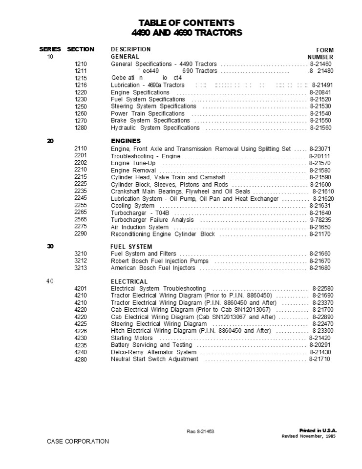
TABLE OF CONTENTS 4490 AND 4690
TRACTORS DESCRIPTION GENERAL
SERIES 10
SECTION
FORM NUMBER
1210 1211 1215 1216 1220 1230 1250 1260 1270 1280
General Specifications - 4490 Tractors
............................... 8-21460
ec449 Gebe ati n io ct4
690 Tractors ......................... .8 21480
Lubrication - 4690a Tractors
8-21491
Engine Specifications ...........................
................... 8-20841
Fuel System Specifications ......................
................... 8-21520 Steering System
Specifications ..................................
... 8-21530 Power Train Specifications
.........................................
8-21540 Brake System Specifications
........................................
8-21550 Hydraulic System Specifications
.................................... 8-21560
20
ENGINES Engine, Front Axle and Transmission
Removal Using Splitting Set ..... 8-23071
Troubleshooting - Engine ........................
................... 8-20111 Engine Tune-Up
..................................................
. 8-21570 Engine Removal .........................
........................... 8-21580 Cylinder
Head, Valve Train and Camshaft ...................
......... 8-21590 Cylinder Block, Sleeves,
Pistons and Rods ...........................
8-21600 Crankshaft Main Bearings, Flywheel and
Oil Seals .................... 8-21610
Lubrication System - Oil Pump, Oil Pan and Heat
Exchanger .......... 8-21620 Cooling System
..................................................
.. 8-21631 Turbocharger - T04B
...............................................
8-21640 Turbocharger Failure Analysis
......................................
9-78235 Air Induction System ....................
........................... 8-21650 Reconditioning
Engine Cylinder Block ..........................
..... 8-21170
2110 2201 2202 2210 2215 2225 2235 2245 2255 2265
2565 2275 2290
30
FUEL SYSTEM Fuel System and Filters
.............................................
8-21660 Robert Bosch Fuel Injection Pumps
.................................
8-21670 American Bosch Fuel Injectors
...................................... 8-21680
3210 3212 3213
40
ELECTRICAL Electrical System Troubleshooting
.................................. 8-22580
Tractor Electrical Wiring Diagram (Prior to
P.I.N. 8860450) ............ 8-21690 Tractor
Electrical Wiring Diagram (P.I.N. 8860450 and
After) .......... 8-23370 Cab Electrical Wiring
Diagram (Prior to Cab SN12013067) ............
8-21700 Cab Electrical Wiring Diagram (Cab
SN12013067 and After) ........... 8-22890
Steering Electrical Wiring Diagram
.................................. 8-22470 Hitch
Electrical Wiring Diagram (P.I.N. 8860450 and
After) ............ 8-23300 Starting Motors
..................................................
.. 8-21420 Battery Servicing and Testing
.......................................
8-20291 Delco-Remy Alternator System
......................................
8-21430 Neutral Start Switch Adjustment
.................................... 8-21710
4201 4210 4210 4220 4220 4225 4226 4230 4235 4240
4280
Printed in U.S.A. Revised November, 1985
Rac 8-21453
CASE CORPOR.ATION
2
SERIES 50
SECTION
DESCRIPTION STEERING
FORM NUMBER
5201 5203 5205 5210 5220 5230 5240 5250 5260 5265
5265 5280
Troubleshooting Solid State Selective Steering
....................... 8-22480
Electronic Steering System ......................
................... 8-23700 Testing Tractor
Steering System .................................
... 8-21720 Steering Column, Pump and Valve
..................................
8-21730 Steering Cylinder .......................
........................... 8-21740 Steering
Lines and Controls ..............................
.......... 8-21750 Rear Steering Valve
................................................
8-21760 Front Steering Priority Valve
........................................
8-21770 Rear Steering Priority Valve
.........................................
8-21780 Rear Steering Check Valve (Prior to
P.I.N. 8858086) .................. 8-22001 Rear
Steering Check Valve (P.I.N. 8858086 and After)
................. 8-26430 Front and Rear Steering
Adjustments ................................
8-21790
60
POWER TRAIN Troubleshooting - RPS-34 Power Shift
Transmission and PTO ........ 8-20370 Testing
RPS-34 Power Shift Transmission and PTO
.................. 8-21800 Torque Limiter Clutch
..............................................
8-21810 RPS-34 Power Shift ......................
.......................... 8-21820 RPS-34 Control
Valve and Linkage ...............................
... 8-21830 Four Speed Transmission
...........................................
8-21840 Hydraulic PTO ...........................
.......................... 8-21850 Axles and
Planetaries ......................................
......... 8-21860 Differentials and Drive Shafts
....................................... 8-21871
6201 6205 6220 6230 6235 6240 6245 6250 6260
70
BRAKES Brake Pedal, Master Cylinder, Service and
Parking Brake ............. 8-21880
7210
HYDRAULICS Troubleshooting - Hitch System
.....................................
8-21890 Electronic Hitch Alignment
.........................................
8-23311 Testing Tractor Hydraulic System
...................................
8-21900 Hydraulic Oil Filters ...................
............................. 8-21910 Hydraulic
Pump ............................................
........ 8-21920 Remote Hydraulic Valves
...........................................
8-21930 Flow Divider and PTO Control Valve
................................. 8-21940 Hitch
System ..........................................
............ 8-21950 Electronic Hitch System
............................................
8-23240 Break-Away Couplings and Portable
Cylinder ........................ 8-20640
80
8202 8203 8205 8210 8225 8250 8255 8280 8281 8290
90
ACCESSORIES Troubleshooting - Air Conditioning
System ..........................
8-21960 Gauging and Testing Air Conditioning
System ....................... 8-21970
Compressor Isolation, Removal, Installation and
Evacuation - Oischarging, Evacuation and Charging
the A. C. System .............. 8-21980 Servicing
Air Conditioner Components ......................
........ 8-21990 Servicing the Cab Blower
...........................................
8-20690 Operators Seat Adjustments
........................................
8-20700 Removal of Tilting Hood, Grille and Side
Panels ...................... 8-22010 Safety
Decal Location ..................................
............ 8-22530
9205 9215 9225
9235 9245 9250 9260 9280
100
HOW IT WORKS Tractor Steering System
............................................
8-22020 Case Solid State Selective Steering
..................................
8-22490 Tractor Hydraulic System
...........................................
8-22030 Case CON TROL Hydraulics
....................................... 8-21350
15201 15205 18201 18225
Rac 8-21453
Revised 11-85
Printed in U.S.A.
3
Section
1210
GENERAL SPECIFICATIONS 4490 TRACTORS
Written In Clear And Simple English
CASE CORPORATION
Rac 8-21460
Printed in U.S.A. August, 1979
4
https//www.ebooklibonline.com Hello dear
friend! Thank you very much for reading. Enter
the link into your browser. The full manual is
available for immediate download. https//www.ebo
oklibonline.com
5
1210-2
SERIAL NUMBERS
ENGINE SERIAL NUMBER PLATE MODEL AND PRODUCT
IDENTIFICATION NUMBER PLATE
- F U L L
- AD D
CAB SERIAL NUMBER PLATE
TRANSMISSION SERIAL NUMBER PLATE
AXLE SERIAL NUMBER PLATE (Front and Rear)
Rac 8-21460
Issued 8-79
Printed in U.S.A.
6
1210-5
DIESEL ENGINE SPECIFICATIONS General
Type
Six Cylinder, Four Stroke Cycle,
Turbocharged, Valve in Cylinder Head
Firing Order ....................................
.........................................
1-5-3-6-2-4 Bore .................................
....................................... 4-5/8
Inches (117.5 mm) Stroke ........................
..................................................
. 5 Inches (127 mm) Piston Displacement
..................................................
.. 504 Cubic Inches (8 259 cm) Compression Ratio
.................................................
....................... 15.75 to 1 Cylinder
Sleeves .........................................
............... Wet Type, Can be Removed Governor
Engine Speed Without Load .......................
....................... 2340 to 2380 RPM Rated
Engine Speed ....................................
.................................. 2200
RPM Engine Idle Speed ...........................
........................................ 725 to
775 RPM Rocker Arm-to-Valve Clearance (Exhaust)
..................................................
0.025 Inch (0.635 mm) (Intake)
..................................................
. 0.015 Inch (0.381 mm) IMPORTANT Rocker A
rm-to- Valve c/earance adjustment must be made
when the engine is not running.
Piston and Rod Rings Per Piston
..................................................
................................ 3 Compression
Rings Per Piston ................................
..................................... 2 Oil Rings
Per Piston ......................................
......................................... 1 Type
Piston Pin ......................................
..................................... Full
Float Type Bearings ..............................
.............. Replacement Bearings Available,
Steel Back with Aluminum or Copper and lead
liners. Main Bearings Quality of Bearings
..................................................
.............................. 7 Type of Bearings
.........................................
Replacement Bearings Available, Steel Back With
Aluminum or Copper and Lead Liners. Engine
Lubrication System
Oil Pressure ........ Type System Oil Pump Oil
Filters (2) Oil Capacity ........ Oil Cooler
. 45 to 60 PSI (310 to 414 kPa)(3.1 to 4.14 bar)
with Engine Warm and Operating at Rated Speed. .
Pressure and Spray with Piston Oil Cooling Gear
Type . Full Flow, Turn on Type, ByPass Valve in
Filter Base. . With Filters, 28 U.S. Quarts (27
litres) Without Filters, 24 U.S. Quarts (23
litres) . Engine Oil
Rac 8-21460
Issued 8-79
Printed in U.S.A.
7
1210-6
Fuel System Fuel Injection Pump
..................................................
...... Robert Bosch, Type PES. Pump Timing
..................................................
. 25 Degrees (BTC) Before Top Center. IMPORTANT
Do not increase past 25 degrees BTC at any time.
The given 25 degrees Gives Minimum Emissions in
Tractor Operation and Longer Engine Life. Fuel
Injectors ........................................
....................... American Bosch, 17
mm. Fuel Transport Pump .........................
................................ Plunger Type, a
Part of the Fuel Injection Pump Governor
.............................................
Variable Speed, Part of the Fuel Injection
Pump First Stage Fuel Filter ....................
.................................... Full Flow,
Turn on Type Second Stage Fuel Filter
..................................................
... Full Flow, Turn on Type Water Trap and Drain
For Fuel Tanks ..........................
Location is in Bottom of Each Fuel Tank Fuel Tank
Capacity ........................................
........ 64 U.S. Gallons (242.3 litres)
Each Tank, 128 U.S. Gallons (484.6 Litres) Total
Fuel Level Gauge .................................
.......... Electric, Location is on Instrument
Cluster Hand Primer Pump ........................
................ Location is on Top of Fuel
Transport Pump Primary Fuel Filter
...................................... Location
is at Bottom of Fuel Transport Pump GENERAL
TRACTOR SPECIFICATIONS Air Intake System Type
.................................................
Dry Type Air Induction System, Two Stage
with Service Indication, Strata Tube. Cooling
System Capacity .................................
................................. 48 U.S. Quarts
(45.4 litres) Type ..............................
......................... Pressure System,
Thermostat Controlled, Bypass Impeller Type Pump
Radiator .........................................
..................... Heavy Duty Fin and Tube
Type Thermostats (2) ............................
............ Start to Open at Approximately 175
F (79 C), Fully Open at 202 F (94 C) Pressure
Cap ..............................................
.......... 10 PSI (69 kPa)(6.9 bar) No
Vent Coolant Level ..............................
........ Low Coolant Warning Lamp on Instrument
Cluster
Rac 8-21460
Issued 8-79
Printed in U.S.A.
8
1210-7
Electrical System Type of System
..................................................
........... 12 volt, Negative Ground Batteries
.......................... Two 12 Volt Batteries
Connected in Parallel, AABM Group Size 30H, Rated
in 1.255 to 1.265 Specific Gravity. Discharge
Rate 300 Amperes at 0 F. Voltage Decrease to 9.2
After 10 Seconds. Voltage Decreases 1.0 Volt per
Cell After S Minutes. Alternator
...............................................
12 Volt, 72 Ampere Output, Negative
Ground Voltage Regulator ........................
......... 12 Volt, Solid State, Inside Component
of Alternator Starting Motor ....................
...................................... 12 Volt
with Solenoid Switch Headlights (2)
............................................. 12
Volt, 40/60 Watt Sealed Beam High-Low Floodlights
(8 max)(Optional) ................................
........... 12 Volt, 50 Watt, Sealed Beam Flasher
Lights (2) With Direction Turn Signals
..................................... 12 Volt,
Amber Lens Rear Flood and Taillight
.................................................
12 Volt, 35 Watt Sealed Beam With Taillight Bulb.
Tractor Electrical System Circuit Breaker
..................... 12 Volt, Dual 50 Ampere
Circuit Breakers Connected in Parallel, 100
Ampere Rat- ing, 80 Ampere Continuing
Capacity. Cab Electrical System Circuit Breaker
............................................. 12
Volt, 20 Ampere Bulb and Lamp Replacement Instrum
ent Cluster Warning Bulbs ........................
.................................. No.
168 Instrument Cluster Illumination Bulbs
..................................................
.... No. 194 Dome Light Bulb ........ .. ....
.... . ........................................
No. 93 Console Light Bulb ........................
................................................
No. 194 Flasher Light Bulbs .....................
.................................................
No. 1156 Headlight Lamps ........................
.................................................
No. 4652 Front and Rear Floodlights
..................................................
............ No. H7606 Rear Flood and
Taillight Lamp ..................................
................................................
No. 4409 Bulb ...................................
...............................................
No. 1156 Fuse and Circuit Breaker
Replacement Wiper ..............................
..................................................
. 7.5 Ampere Instrument Panel Lights
..................................................
.............. 5.0 Ampere Headlights Low Beam
..................................................
................. 15 Ampere Accessories
..................................................
.......................... 15 Ampere Blowpr
..................................................
.............................. 15 Ampere Radios
..................................................
............................... 3.0
Ampere Headlight High Beam .......................
............................................ 15
Ampere Key Switch ...............................
............................................. 20
Ampere Cigarette Lighter ........................
...............................................
15 Ampere Console Light .........................
................................................
3.0 Ampere Rear Floodlights (Optional)
..................................................
........... 20 Ampere Rear Steering
..................................................
....................... 3.0 Ampere Dome Light
..................................................
......................... 3.0 Ampere Flasher
Warning Lights ..................................
............................... 15 Ampere Front
Floodlights (Optional) ..........................
.................................. 20
Ampere Sound Warning for ........................
............... Transmission Filters, Engine Oil
Pressure, Coolant Temperature and Hand Brake.
Rac 8-21460
Issued 8-79
Printed in U.S.A.
9
1210-8
Tractor Brakes Type ............................
................................. Hydraulic
Actuated, Self-Adjusting, Several Plate Dry
Type. Parking Brake Type .......................
................... Cable Actuated by over center
Type Handle Adjustable from Operators Seat.
Several Plate Type. Power Shift
Transmission Type ...............................
............. Three Speed Compound Planetary with
Hydraulically Actuated Clutches and Four Speed
Gear Section. Gear Selection ....................
...................... 12 Speeds Forward and Four
Speeds Reverse Shift Control .....................
............ Hydraulic Power Shift Controlled by
a Mechanical Shifter Actuated by Levers on the
instrument Console. Oil Cooler
..................................................
Transmission, Hydraulic and Steering Oil Oil
Type .............................................
............ Case PTF Power Transmission
Fluid Oil Refill Capacity (With PTO and Hitch)
................................... 32 U.S.
Quarts (30.3 litres) (No PTO) ...................
............................................. 30
U.S. Quarts (28.4 litres) Includes 8 Qts (7.6
litres) for Filter Change. Hydrostatic Front
Power Steering Oil Supply .......................
........... Hydraulic Pump, 15 gpm (56.8
litres/min) at 2200 RPM and 2000 PSI (13 790
kPa)(137.9 bar). 10 gpm (38 litres/min) for front
steering and 5 gpm (19 litres/min) returns to
filters. Relief Valve Pressure
................................................
2250 PSI (15 414 kPa)(154.1 bar) Front Steering
Cylinders .......................................
.... Two Cylinders with two way action Steering
Pump ......................................
Hydrostatic Type, Actuated by the steering
wheel Rear Power Steering Oil Supply
..................................... Hydraulic
Pump, 10 gpm (37.85 litres/min) at 2200
RPM Relief Valve Pressure ........................
.................. 1650 to 1900 PSI (11 377 to 13
101 kPa) (113.8 to 131 bars) Rear Steering
Cylinders .......................................
... Two Cylinders with Two Way Action Controls
..........................................
Selective Steering with Automatic rear Steering
with all Wheels Controlled by steering wheel or
rear wheels Controlled by a hydraulic-electric
servo system with three position selection switch
and a toggle switch on operator console. Axle
Differential and Planetaries Front and Rear
.......................................... Spiral
Bevel with Planetary Reduction in
hub. Differential Oil Capacity ...................
.................. 19 U.S. Quarts (18 litres)
Each Differential Planetary Oil Capacity
...................................... 11 U.S.
Quarts (10.4 litres) Each Planetary
Revised 11-85
Printed in U.S.A.
Rac 8-21460
10
1210-9
Hitch System Type Control ......................
..................................................
.... Hand Lever Type Valve .......................
............................... Three Position -
Lift, Hold and Lower Type Draft Arms
..................................... Rigid,
Swing Type with Manual Float Adjustment Type
Hitch ...........................................
...................... Three Point, Category
III Hitch Coupler (Available) ...................
.............................................
Category III Remote Hydraulic System Pump
............................................
Axial Piston Pump, Pressure and Flow
Compensated Type Remote Valve ....................
.................... Closed Center, Two to Four
Sections, Hand Lever Control, Variable Flow
Control for Each Section. Pump Capacity at 2200
RPM ..............................................
31 GPM (117.4 litres/min) at 2000 PSI (13 790
kPa)(137.9 bar). Max System Pressure
..................................................
2250 PSI (15 503 kPa)(155 bar) Couplings
...................................... ASAE R366
Standard, Fast Removal, Break Away Type Hydraulic
Charge Pump ......................................
.. 43 GPM (162.8 litres/min) at 2200 RPM and 100
PSI (240 kPa)(2.4 bar). Charge Circuit Relief
Valve Pressure ...................................
..... 35 PSI (241 kPa)(2.41 bar) Power
Takeoff Type Clutch ............................
.........................................
Hydraulic Actuated Rotation ......................
..................................................
......... Clockwise Spline Size
.................................................
21 Splines, 1-3/8 inch (34.9 mm) Diameter Engine
Speed 2200 RPM ..................................
.................... 1000 RPM Shaft Speed Drawbar
Standard or Yoke Type
.............................................
Full Swing, Roller Mount, Takes a 1-1/2 inch
(38.1 mm) Diameter Pin
Rae 8-2J 460
Issued 8-79
Printed in U.S.A.
11
2110-8
SPECIAL TORQUES U.S. Value Engine To Torque Tube
(1/2 inch, Grade S Bolts) . 80 to 96 lb
ft Engine To Torque Tube (1/2 inch, Grade 8
Bolts) .......... 110 to 132 lb ft
Metric Value 109 to 130 Nm (10.9 to 13.0 kgm) 149
to 179 Nm (14.9 to 17.9 kgm) 366 to 439 Nm (36.6
to 43.9 kgm) 20 to 27 Nm (2.0 to 2.7 kgm) 48 to
57 Nm (4.8 to 5.7 kgm) 109 to 130 Nm (10.9 to
13.0 kgm) 203 to 244 Nm (20.3 to 24.4 kgm) 814 to
976 Nm (81.4 to 97.6 kgm) 542 to 651 Nm (54.2 to
65.1 kgm)
Engine To Torque Tube (3/4 inch, Grade S Bolts)
.......... 270 to 324 lb ft
Seal Plate Inner Capscrews .......................
.......... 15 to 20 lb ft
Seal Plate Outer Capscrews ......................
.......... 35 to 42 lb ft
Seal Plate (1/2 inch Bolts) .....................
............. 80 to 96 lb ft
Side Rail Bolts ..................................
......... 150 to 180 lb ft
Axle Retaining Bolts (7/8 inch For 70 and 90
Series Tractors) ... 600 to 720Ib ft
Axle Retaining Bolts (7/8 inch For 94 Series
Tractors) ...... 400 to 480 lb ft
Axle Retaining Bolts (1-1/8 inch For 70 and 90
Series Tractors) ...............................
1,300 to 1,400 lb h
1 763 to 1 898 Nm (176.3 to 189.8 kgm) 1 085 to 1
193 Nm (108.5 to 119.3 kgm) 48 to 57 Nm (4.8 to
5.7 kgm) 61 to 73 Nm (6.1 to 7.3 kgm) 109 to 130
Nm (10.9 to 13.0 kgm) 149 to 179 Nm (14.9 to 17.9
kgm) 203 to 244 Nm (20.3 to 24.4 kgm) 366 to 439
Nm (36.6 to 43.9 kgm) 48 to 57 Nm (4.8 to 5.7
kgm) 48 to 57 Nm (4.8 to 5.7 kgm) 61 to 73
Nm (6.1 to 7.3 kgm) 203 to 244 Nm (20.3 to 24.4
kgm)
Axle Retaining Bolts (1-1/8 inch For 94 Series
Tractors) .... 800 to 880 lb ft Differential
Drive Shaft (3/8 inch, Grade S Bolts)
............. 35 to 42 lb ft Differential Drive
Shaft (3/8 inch, Grade 8 Bolts) ............. 45
to 54 lb ft Differential Drive Shaft (1/2 inch,
Grade S Bolts) ............. 80 to 96 lb ft
Differential Drive Shaft (1/2 inch, Grade 8
Bolts) ........... 110 to 132 lb h
Rear Transmission Bracket Bolts
......................... 150 to 180 lb ft
Front Transmission Spacer Bolts
......................... 270 to 324 lb h
Transmission Oil Manifold Bolts
............................ 35 to 42 Ib ft
PTO Universal Joint (3/8 inch, Grade S Bolts)
................ 35 to 42 lb ft
PTO Universal Joint (3/8 inch, Grade 8 Bolts)
................ 45 to 54 lb ft
Torque Tube Spacer Bolts .........................
....... 150 to 180 lb ft
Rac 8-23071
Issued 9-84
Printed in U.S.A.
12
21 o-e
SPECIAL TOOLS CAS-10500 FOUR WHEEL DRIVE
SPLITTING SET COMPLETE
2470 AND 2670 ENGINE YOKE (PART OF COMPLETE SET)
CAS-10500-6 TRACK ASSEMBLY 2 ENDS 3 CENTER
CAS-10501 ONE SECTION OF CENTER TRACK
ENGINE SAFETY STANDS (PART OF COMPLETE SET)
CAS-10500-5 FRAME LOCKS (2)
CAS-10500-1 SIDE FRAME JACKS (2)
CAS-10500-3 TRANSMISSION CART
CAS-10500-4 AXLE CART
CAS-10500-2 ENGINE CART Issued 9-84 Printed in
U.S.A.
Rac 8-23071
13
2110-10 Disconnects For Engine, Front Axle And
Transmission Removal
STEP 1
STE
Pull the latch on each side of the tractor to
release the hood.
Remove the two side panels. To remove the sheet
metal and radiator on the 2470 and 2670, see Sec-
tion 2032 in your Case Service Manual.
STEP 2
STEP 5
RADIATOR DRAINCOCK
Lift the hood until the front hinge is in the
lock position.
Drain the coolant from the radiator.
STEP 3
STEP 6
Remove the battery ground cables (negative
black) from the starting motor.
Make sure the hood is completely held in the up
position by the hinge lock.
Rac 8-23071
Issued 9-84
Printed in U.S.A.
14
2110-11
STEP 10
STEP 7
Remove the battery positive (red) cables from the
solenoid on the starting motor.
Remove the two clamps that hold the muffler tube
to the support bracket. Remove the muffler and
tube from the tractor.
STEP 8
STEP 11
Put tape on the end of the positive (red) battery
cables to prevent spark caused by an accident.
Muffler removed from the tractor.
STEP 12
STEP 9
Disconnect the tachometer drive cable from the
engine.
Remove the upper clamp that holds the aspirator
hose to the muffler.
Rac 8-23071
Issued 9-84
Printed in U.S.A.
15
2110-12
STEP 13
STEP 16
T H
Remove the pyrometer sensing unit.
Disconnect the RH oil cooler hose at the inside
of the RH side rail.
STE
STEP 17
DISCONNECT HERE
Disconnect the low pressure air conditioner hose
at the coupler.
Disconnect the LH oil cooler hose at the inside
of the LH side rail.
NOTE Disconnecting the air conditioner hoses at
the coupler will prevent the loss of
refrigerant. STEP 15
DISCONNECT HEf
REMOVE BOLT
Remove the retaining bolt for the wiring harness
connector. Disconnect the air conditioner hose
from the cab to the receiver-drier.
Issued 9-84
Printed in U.S.A.
Rac 8-23071
16
2110-13
STEP 22 (For 70 and 90 Series Tractors Only)
bz PANEL BRACE
STEP 19 or 70 and 90 Series Tractors Only)t
Remove the pane I brace from the panels.
Pull the wiring harness connector from the
firewall connector. Disconnect small connectors
from the cab harness as needed.
STEP 23 (For 94 Series Tractors Only)
STEP 20 (For 94 Series Tractors
Only) TRANSMISSION HARNESS ENGINE HARNESS
REMOVE BOLT
Remove the retaining bolt from the adjustment bar
for the hood rear side panels.
Loosen the bolt that retains the engine harness
connector to the firewall connector.
STEP 24 (For 94 Series Tractors Only)
STEP 21 (For 94 Series Tractors Only)
Rem ove the adjustment bar. Disconnect the
engine harness connector from the firewall
connector.
Rae 8-23071
Issued 9-84
Pri nted in U.S.A.
17
2110-14 STEP 25
Remove the heater hose from the shutoff valve.
S.TEP 29
STEP 26
DISCONNECT HERE
Remove the heater return hose from the water pump
housing.
Remove the throttle cable from the fuel pump and
throttle bracket.
STEP 27
ENGINE STOP CABLE
Remove the engine stop cable from the fuel pump
and throttle bracket.
Disconnect the fuel return line from the fuel
pump.
Rac 8-23071
Issued 9-84
Printed in U.S.A.
18
Suggest If the above button click is invalid.
Please download this document first, and then
click the above link to download the complete
manual. Thank you so much for reading
19
2110-15
STEP 34 (2470, 2670, 4490, 4690, 4494 and
4694 ractors Only)
STEP 31
DRAIN PLUG
Remove the seal plate.
Remove the drain plug from the torque tube and
drain the torque tube oil.
STEP 35 (For 90 and 94 Series Tractors Only)
STEP 32 (2470, 2670, 4490, 4690, 4494 and 4694
factors Only)
/2 BOLTS
Remove the cover and gasket from the wiring junc-
tion box on the front axle.
Remove the 1/2 bolts and washers from the tor-
que tube seal plate.
STEP 36 (For 90 and 94 Series Tractors Only)
STEP 33
(2470, 2670, 4490, 4690, 4494 and 4694 ractors Only) BOLTS (2470, 2670, 4490, 4690, 4494 and 4694 ractors Only) BOLTS
Use a small knife to cut the insulation tubes
from each of the three wires.
Remove the 3/8 bolts and washers from the
tor- que tube seal plate.
NOTE A 3f8 inch-12 point universal socket is
needed to remove the four center retaining bolts.
Issued 9-84
Printed in U.S.A.
Rac 8-23071
20
https//www.ebooklibonline.com Hello dear
friend! Thank you very much for reading. Enter
the link into your browser. The full manual is
available for immediate download. https//www.ebo
oklibonline.com
Recommended
CrystalGraphics Presentations


