
CASE IH JX1080U Tractor Service Repair Manual Instant Download
Title:
CASE IH JX1080U Tractor Service Repair Manual Instant Download
Description:
CASE IH JX1080U Tractor Service Repair Manual Instant Download –
Number of Views:0
Title: CASE IH JX1080U Tractor Service Repair Manual Instant Download
1
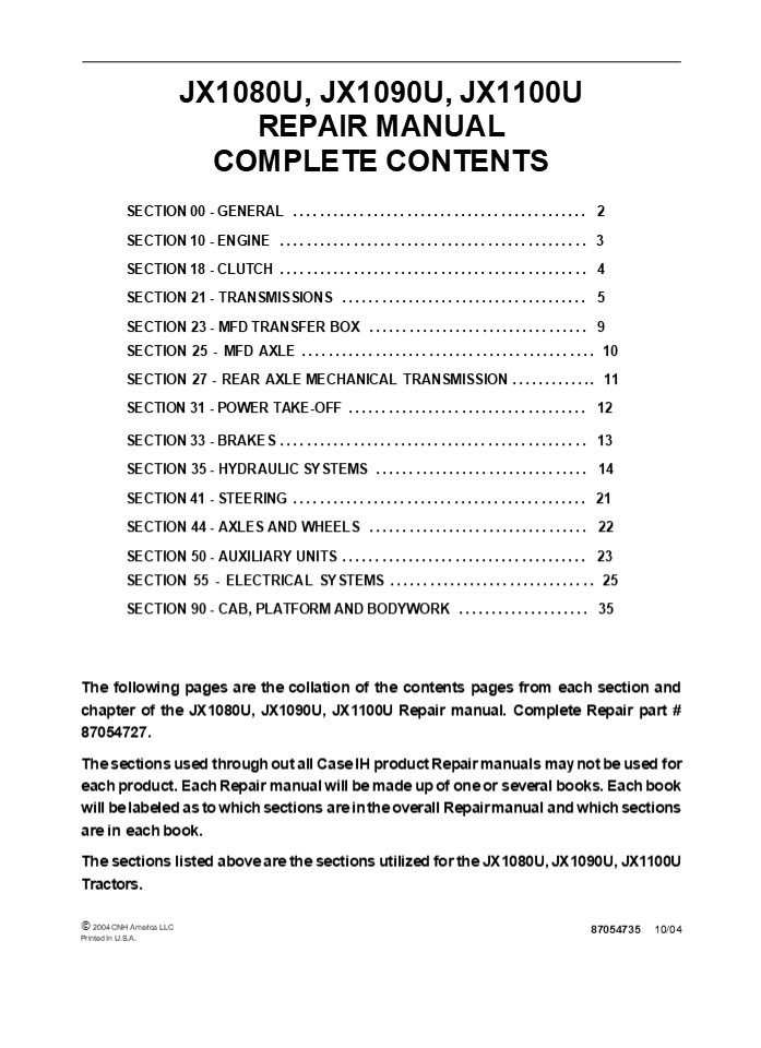
JX1080U, JX1090U, JX1100U REPAIR MANUAL
COMPLETE CONTENTS
SECTION 00 - GENERAL .............................
............... 2 SECTION 10 - ENGINE
..............................................
3 SECTION 18 - CLUTCH ............................
.................. 4 SECTION 21 - TRANSMISSIONS
..................................... 5 SECTION
23 - MFD TRANSFER BOX ............................
..... 9 SECTION 25 - MFD AXLE ....................
........................ 10 SECTION 27 - REAR
AXLE MECHANICAL TRANSMISSION ............. 11
SECTION 31 - POWER TAKE-OFF ......................
.............. 12 SECTION 33 - BRAKES
..............................................
13 SECTION 35 - HYDRAULIC SYSTEMS
................................ 14 SECTION 41 -
STEERING .........................................
... 21 SECTION 44 - AXLES AND WHEELS
................................. 22 SECTION 50 -
AUXILIARY UNITS ..................................
... 23 SECTION 55 - ELECTRICAL SYSTEMS
............................... 25 SECTION 90 -
CAB, PLATFORM AND BODYWORK .................... 35
The following pages are the collation of the
contents pages from each section and chapter of
the JX1080U, JX1090U, JX1100U Repair manual.
Complete Repair part 87054727. The sections
used through out all Case IH product Repair
manuals may not be used for each product. Each
Repair manual will be made up of one or several
books. Each book will be labeled as to which
sections are in the overall Repair manual and
which sections are in each book. The sections
listed above are the sections utilized for the
JX1080U, JX1090U, JX1100U Tractors.
? 2004 CNH America LLC Printed In U.S.A.
87054735 10/04
2
SECTION 00 - GENERAL - CHAPTER 1
1
SECTION 00 - GENERAL Chapter 1 -
General CONTENTS
Description Page General Instructions
..................................................
.......... 3 Health and Safety ...................
...........................................
5 Precautionary Statements .......................
.............................. 15 Safety
..................................................
.................... 16 Ecology and the
Environment ......................................
............ 19 Minimum Hardware Tightening
Torques .........................................
20 Federal Emissions Warranty ...................
................................ 22 California
Emission Control Warranty Statement
.................................. 23 Filling and
Topping-Up Operations ............................
.................. 25
Section
3
SECTION 00 - GENERAL - CHAPTER 1 WARNING WARNING
2
All maintenance and repair work described in
this manual must be performed exclusively by
CASE IH service technicians in strict accordance
with the instructions given and using any
specific tools necessary.
The Manufacturer and all organizations belong-
ing to the Manufacturer's distribution network,
including but not restricted to national,
regional or local distributors, will accept no
responsibility for personal injury or damage to
property caused by abnormal function of parts
and/or compo- nents not approved by the
Manufacturer, including those used for
maintenance and/or repair of the product
manufactured or marketed by the Manufacturer. In
any case, the product manufactured or marketed
by the Manufacturer is covered by no guarantee
of any kind against personal injury or damage to
property caused by abnormal function of parts
and/or components not approved by the
Manufacturer.
WARNING
Anyone who performs the operations described
herein without strictly following the
instructions is personally responsible for
resulting injury or damage to property.
4
https//www.ebooklibonline.com Hello dear
friend! Thank you very much for reading. Enter
the link into your browser. The full manual is
available for immediate download. https//www.eb
ooklibonline.com
5
SECTION 00 - GENERAL - CHAPTER 1
3
GENERAL INSTRUCTIONS
IMPORTANT NOTICE All maintenance and repair
operations described in this manual should be
carried out exclusively by the authorised
workshops. All instructions detailed should be
carefully observed and special equipment
indicated should be used if necessary. Everyone
who carries out service operations described
without carefully observing these prescrip-
tions will be directly responsible of deriving
damages.
- Take care to insert the seal perpendicularly to
its seat while you are pressing it. Once the
seal is settled, ensure that it contacts the
thrust element, if required - To prevent damaging the sealing lip against the
shaft, place a suitable protection during
installation.
O RINGS Lubricate the O rings before inserting
them into their seats. This will prevent the O
rings from roll over and twisting during
mounting, which will jeopardize sealing.
SHIMMING At each adjustment, select adjusting
shims, measure them individually using a
micrometer and then sum up recorded values. Do
not rely on measuring the whole shimming set,
which may be incorrect, or on the rated value
indicated for each shim.
SEALERS Apply silicone/gasket eliminator over the
mating surfaces marked with an X. Before
applying the sealer, prepare the surface as
follows
ROTATING SHAFT SEALS To correctly install
rotating shaft seals, observe the following
instructions
- remove possible scales using a metal brush
- thoroughly degrease the surfaces using one of
the following cleaning agents trichlorethylene,
diesel fuel or a water and soda solution.
- Let the seal soak into the same oil as it will
seal for at least half an hour before mounting - Thoroughly clean the shaft and ensure that the
shaft working surface is not damaged - Place the sealing lip towards the fluid. In case
of a hydrodynamic lip, consider the shaft
rotation direction and orient grooves in order
that they deviate the fluid towards the inner
side of the seal - Coat the sealing lip with a thin layer of
lubricant (oil rather than grease) and fill the
gap between the sealing lip and the dust lip of
double lip seals with grease - Insert the seal into its seat and press it down
using a flat punch. Do not tap the seal with a
hammer or a drift
BEARINGS It is advisable to heat the bearings to
80? to 90?C (176? to 194?F) before mounting them
on their shafts and cool them down before
inserting them into their seats with external
tapping.
SPRING PINS When mounting split socket spring
pins, ensure that the pin notch is oriented in
the direction of the effort to stress the
pin. Spiral spring pins should not be oriented
during installation.
6
SECTION 00 - GENERAL - CHAPTER 1
4
- GENERAL INSTRUCTIONS
- PRECAUTIONARY NOTICE
- Only authorized workshops should carry out
maintenance and repair operations on the tractor,
or tractor compo- nents. Carefully observe all
instructions, safety precautions, and the use of
equipment such as special tools, as detailed in
this manual. Damage to the tractor, or injury to
personnel is the direct responsibility of anyone
who fails to observe these precautions. - EQUIPMENT NOTICE
- The equipment proposed in this manual is
- Designed and studied expressly for use on Case IH
tractors - Necessary for adequate and reliable repair of the
tractor - Strictly tested for the efficient and long
lasting life cycle of the tractor - SPARE PARTS NOTICE
- Genuine CASE IH spare parts guarantee the same
quality, safety and life cycle as original
components. These parts bear the logo. - GENERAL NOTICES
- In this manual, the description FRONT, REAR,
RIGHT- HAND and LEFT- HAND refer to the view
seen by the operator while in the operators
seat, looking in the direction in which the
tractor normally moves. - Wear limits detailed in this manual, although
advised, are not binding.
7
SECTION 00 - GENERAL - CHAPTER 1
5
HEALTH AND SAFETY CONTENTS Description Page HEAL
TH AND SAFETY PRECAUTIONS ........................
................................. 5 ACIDS AND
ALKALIS ..........................................
............................... 6 ADHESIVES AND
SEALERS - see Fire ...............................
.......................... 6 ANTIFREEZE - see
Fire, Solvents e.g. Isopropanol, Ethylene Glycol,
Methanol. ...................... 6 ARC WELDING -
see Welding. .....................................
............................ 7 BATTERY ACIDS -
see Acids and Alkalis. ...........................
............................ 7 BRAKE AND CLUTCH
FLUIDS (Polyalkylene Glycols) - see Fire.
................................... 7 BRAZING -
see Welding. .....................................
................................. 7 CHEMICAL
MATERIALS - GENERAL - see Legal Aspects.
........................................ 7 DOS
..................................................
..................................... 7 DO NOTS
..................................................
................................. 8 CORROSION
PROTECTION MATERIALS - see Solvents, Fire.
.................................... 8 DUSTS
..................................................
................................... 8 ELECTRIC
SHOCK ............................................
............................... 8 EXHAUST FUMES
..................................................
......................... 9 FIBRE INSULATION -
see Dusts. .......................................
....................... 9 FIRE - see Welding,
Foams, Legal Aspects. ............................
......................... 9 FIRST AID
..................................................
................................ 9 FOAMS -
Polyurethane - see Fire. .........................
.................................... 9 FUELS -
see Fire, Legal Aspects, Chemicals - General,
Solvents. ................................ 10
GAS CYLINDERS - see Fire. ........................
........................................
10 GENERAL WORKSHOP TOOLS AND EQUIPMENT
............................................. 11
LEGAL ASPECTS ....................................
.......................................
11 LUBRICANTS AND GREASES ........................
........................................
11 PAINTS - see Solvents and Chemical Materials -
General. .......................................
12 SOLDER - see Welding. ........................
............................................
12 SOLVENTS - see Chemical Materials - General
Fuels (Kerosene), Fire. ..........................
. 13 SUSPENDED LOADS ............................
...........................................
13 WELDING - see Fire, Electric Shock, Gas
Cylinders. .......................................
..... 13
HEALTH AND SAFETY PRECAUTIONS Many of the
procedures associated with vehicle maintenance
and repair involve physical hazards or other
risks to health. This section lists, alphabeti-
cally, some of these hazardous operations and the
materials and equipment associated with them. The
precautions necessary to avoid these hazards are
identified. The list is not exhaustive and all
operations and procedures and the handling of
materials, should be carried out with health and
safety in mind.
8
SECTION 00 - GENERAL - CHAPTER 1
6
ACIDS AND ALKALIS -- see Battery acids, e.g.
caustic soda, sulfuric acid. Used in batteries
and cleaning materials. Irritant and corrosive to
the skin, eyes, nose and throat. Causes
burns. Avoid splashes to the skin, eyes and
clothing. Wear suitable protective gloves and
goggles. Can destroy ordinary protective
clothing. Do not breathe mists. Ensure access to
water and soap is readily available for
splashing accidents.
Provide adequate ventilation and avoid skin and
eye contact. Follow manufacturers instructions.
Anaerobic, Cyanoacrylate and other Acrylic
Adhesives Many are irritant, sensitizing or
harmful to the skin. Some are eye
irritants. Skin and eye contact should be avoided
and the manufacturers instructions
followed. Cyanoacrylate adhesives (super-
glues) must not contact the skin or eyes. If
skin or eye tissue is bonded cover with a clean
moist pad and get medical attention. do not
attempt to pull tissue apart. Use in well
ventilated areas as vapours can cause irritation
of the nose and eyes. For two- pack systems see
Resin based adhesives/ sealers.
ADHESIVES AND SEALERS -- see Fire Highly
Flammable, Flammable, combustible. Generally
should be stored in No Smoking areas
cleanliness and tidiness in use should be
observed, e.g. disposable paper covering benches
should be dispensed from applicators where
possible contain- ers, including secondary
containers, should be labelled. Solvent based
Adhesives/Sealers - See Solvents. Follow
manufacturers instructions. Water based
Adhesives/Sealers Those based on polymer
emulsions and rubber lattices may contain small
amounts of volatile toxic and harmful chemicals.
Skin and eye contact should be avoided and
adequate ventilation provided during use. Follow
manufacturers instructions. Resin based
Adhesives/Sealers - e.g. epoxide and
formaldehyde resin based. Mixing should only be
carried out in well ventilated areas as harmful
or toxic volatile chemicals may be
released. Skin contact with uncured resins and
hardeners can result in irritation dermatitis
and absorption of toxic or harmful chemicals
through the skin. Splashes can damage the eyes.
Isocyanate (Polyurethane) Adhesives/ Sealers --
see Resin based Adhesives.
Individuals suffering from asthma or respiratory
allergies should not work with or near these
materials as sensitivity reactions can
occur. Any spraying should preferably be carried
out in exhaust ventilated booths removing
vapours and spray droplets from the breathing
zone. Individuals working with spray
applications should wear supplied air
respirators.
ANTIFREEZE -- see Fire, Solvents e.g.
Isopropanol, Ethylene Glycol, Methanol. Highly
Flammable, Flammable, Combustible. Used in
vehicle coolant systems, brake air pressure
systems, screenwash solutions. Vapours given off
from coolant antifreeze (glycol) arise only when
heated. Antifreeze may be absorbed through the
skin in toxic or harmful quantities. Antifreeze
if swallowed is fatal and medical attention must
be found immediately.
9
SECTION 00 - GENERAL - CHAPTER 1
7
ARC WELDING -- see Welding.
The effects of excessive exposure to chemicals
may be immediate or delayed briefly experienced
or permanent cumulative superficial life
threatening or may reduce life- expectancy.
BATTERY ACIDS -- see Acids and Alkalis. Gases
released during charging are explosive. Never
use naked flames or allow sparks near charging
or recently charged batteries.
DOS Do remove chemical materials from the skin
and clothing as soon as practicable after
soiling. Change heavily soiled clothing and
have it cleaned. Do carefully read and observe
hazard and precaution warnings given on material
containers (labels) and in any accompanying
leaflets, poster or other instructions. Material
health and safety data sheets can be obtained
from Manufacturers. Do organise work practices
and protective clothing to avoid soiling of the
skin and eyes breathing vapours/aerosols/dusts/f
umes inadequate contain- er labelling fire and
explosion hazards. Do wash before job breaks
before eating, smoking, drinking or using toilet
facilities when handling chemical materials. Do
keep work areas clean, uncluttered and free of
spills. Do store according to national and local
regulations. Do keep chemical materials out of
reach of children.
BRAKE AND CLUTCH FLUIDS (Polyalkylene Glycols) --
see Fire. Combustible. Splashes to the skin and
eyes are slightly irritating. Avoid skin and eye
contact as far as possible. Inhalation of vapour
hazards do not arise at ambient temperatures
because of the very low vapour pressure.
BRAZING -- see Welding.
CHEMICAL MATERIALS - GENERAL -- see Legal
Aspects. Chemical materials such as solvents,
sealers, adhesives, paints, resin foams, battery
acids, antifreeze, brake fluids, oils and grease
should always be used with caution and stored
and handled with care. They may be toxic,
harmful, corrosive, irritant or highly
inflammable and give rise to hazardous fumes and
dusts.
10
SECTION 10 - ENGINE - CHAPTER 1
1
SECTION 10 - ENGINE Chapter 1 - Engine CONTENTS
Description Page Specifications
..................................................
................ 3 Tightening Torques
..................................................
......... 12 Torque Settings with Angle
.................................................
13 Special Tools .................................
............................... 14 Description
and Operation ....................................
................. 15 Sectional Views
..................................................
........ 15 Troubleshooting ......................
........................................
22 Overhaul ......................................
.............................. 26 Engine
..................................................
................ 26 Removal ......................
.......................................
26 Installation ..................................
.......................... 43 Disassembly
..................................................
........ 46 Assembly .............................
............................... 57 Checks,
Measurements and Repairs .........................
............... 80 Cylinder Block Liners
..................................................
80 Crankshaft ...................................
........................ 83 Connecting Rods
..................................................
.... 85 Pistons ..................................
............................. 87 Camshaft and
Valves ...........................................
....... 91 Cylinder Head .........................
............................... 95 Oil Pressure
Indicator ........................................
.......... 96 Oil Filter .........................
..................................... 96 Cooling
System ...........................................
............ 97 Crankshaft Front Seal
..................................................
... 98 Removal ...................................
.......................... 98 Installation
..................................................
......... 100 Crankshaft Rear Seal
..................................................
.. 101 Removal ...................................
......................... 101 Installation
..................................................
......... 102 Valve Tappet and Rocker Arm
.............................................
104 Clearance Adjustment .........................
........................ 104
Operation
10 001 10
10 102 74
10 106 12
11
2
SECTION 10 - ENGINE - CHAPTER 1
Operation 10 218 30
Description Page Fuel Injectors
..................................................
......... 107 Removal ............................
................................ 107 Installation
..................................................
......... 108 Bosch Injection Pump
..................................................
.. 110 Removal ...................................
......................... 110 Installation
..................................................
......... 113 Timing Procedure ...................
................................. 115 Fuel
Circuit Air Bleeding .............................
.................. 117 Turbocharged Diesel Engine
..............................................
118 Coolant Pump .................................
.......................... 121 Removal
..................................................
.......... 121 Installation ......................
.....................................
122 Thermostart Valve ............................
........................... 123 Removal
..................................................
.......... 123 Installation ......................
.....................................
124 Radiator .....................................
........................... 125 Removal
..................................................
.......... 125 Installation ......................
..................................... 129 Coolant
Pump and Alternator Drive Belts
.................................... 131 Tension
Adjustment .......................................
............ 131
10 246 14
10 402 10
10 402 30
10 406 10
10 414 10
12
SECTION 10 - ENGINE - CHAPTER 1
3
SPECIFICATIONS
4 Cylinders
Engine, type
- model JX1080U - Naturally Aspirated .................. F4CE0404CD681
- model JX1090U - Turbocharged ...................... F4CE0454ED681
- model JX1100U - Turbocharged ...................... F4CE0454DD681
Cycle ................................................. diesel, 4- stroke
Fuel injection .......................................... direct
Number of cylinders in line ............................... 4
Piston diameter (bore)
- model JX1080U - JX1090U - JX1100U ................ 4.0944 in. (104 mm)
Piston stroke ........................................... 5.1968 in. (132 mm)
Total displacement
- model JX1080U - JX1090U - JX1100U ................ 273.67 in3. (4.5L)
Compression ratio for Models JX1080U - JX1090U - JX1100U 17.51
Maximum power
- model JX1080U - F4CE0404CD681 .................. 60 kW (80 HP)
- model JX1090U - F4CE0454ED681 .................. 67 kW (90 HP)
- model JX1100U - F4CE0454DD681 .................. 73.5 kW (98 HP)
Rated speed ........................................... 2500 rev/min
Maximum Torque _at_ 1400 rev/min
- Maximum torque model JX1080U - F4CE0404CD681 . . 320 Nm (236 lb.-ft.)
- Maximum torque model JX1090U - F4CE0454ED681 . . 350 Nm (258 lb.-ft.)
- Maximum torque model JX1100U - F4CE0454DD681 . . 370 Nm (272 lb.-ft.)
Number of main bearings ................................ 5
Sump ................................................. structural, cast iron
(continued)
13
4
SECTION 10 - ENGINE - CHAPTER 1
(cont)
4 Cylinders
Lubrication ........................................... Pump drive ............................................ Engine speed/oil pump speed ratio ........................ Oil cleaning ............................................ forced, with lobe pump camshaft 11 mesh filter on oil intake and filtering cartridge on delivery line
Normal oil pressure with motor warmed- up at slow idling speed ..................................... 17.4 psi (1.2 bar)
at fast idling speed ...................................... 55.1 psi (3.8 bar)
Cooling system ....................................... coolant circulation
Radiator on Models JX1080U - JX1090U - JX1100U ........ 4 rows of vertical pipes with copper fins
Fan, attached to the pulley ............................... intake, in plastic with 11 blades
Coolant pump .......................................... centrifugal vane- type
Engine speed/coolant pump speed ratio ................... Coolant thermometer ................................... Temperature ranges corresponding to each section - Initial blue section ..................................... - Middle green section (normal working conditions) ......... - Final red section ...................................... 11.977 colored scale divided into 3 sections 104 to 140 ?F (40? to 60 ?C) 140 to 230 ?F (60? to 110 ?C) 230 to 248 ?F (110? to 120 ?C)
Temperature control .................................... via thermostat valve
- initial opening ....................................... 177.0 ? 35.6 ?F (81 ? 2 ?C)
Timing system ........................................ overhead valves operated by tappets, rods and rocker arms via the camshaft located in the engine block the camshaft is driven by the crankshaft using straight- tooth gears
Intake - start before T.D.C. .................................. - end after B.D.C. .................................... Exhaust - start before B.D.C. .................................. - end after T.D.C. .................................... Valve- rocker arm clearance (with engine cold) - intake ............................................. - exhaust ............................................ 10?? 30? 10?? 30? 64? 26? 0.01? 0.001 in (0.30 ? 0.05 mm) 0.02 ? 0.001in (0.55 ? 0.05 mm)
For further timing system technical data ................... see page 9
(continued)
14
SECTION 10 - ENGINE - CHAPTER 1
5
(cont)
4 Cylinders
Fuel system Air cleaning ............................................ Fuel pump ............................................. Fuel filtering ........................................... Minimum fuel flow rate with pump shaft rotating at 1800 rpm . . Cam operated .......................................... BOSCH injection pump .................................. All- speed governor, incorporated in pump BOSCH ............................................... Automatic advance regulator, incorporated in pump BOSCH ............................................... For further fuel system technical data Fixed advance (pump setting for start of delivery before TDC) - Pressure setting - Injection order, and other information re- garding the BOSCH pump ............................... dual cartridge dry air filter, with clogged filter indicator with centrifugal pre- filter and automatic dust ejector with double diaphragm through wire filter in fuel supply pump, and replaceable cartridge on delivery line to injection pump 33.7 g/h (127.6 l/h) engine timing rotating distributor type centrifugal counterweights hydraulic refer to the data for the relevant engine type in the table on page 3
15
SECTION 10 - ENGINE - CHAPTER 1
15
DESCRIPTION AND OPERATION SECTIONAL VIEWS
MIF1096A
1
View of JX1080U of 60 kW (80 HP)
16
16
SECTION 10 - ENGINE - CHAPTER 1
model JX1090U
MIF1097A
2
View of JX1090U tractor engines of 67 kW (90 HP)
and JX1100U of 73.5 kW (98 HP)
17
SECTION 10 - ENGINE - CHAPTER 1 17
Oil
path under pressure Oil return path under
gravity MIF1098A
3
Lubrication diagram for engines mod. JX1090U and
JX1100U
The pressurized lubrication system contains the
fol- lowing components
- by- pass valve to cut off clogged oil filter,
incorpo- rated in the cooler assembly - cartridge oil filter.
- oil pump, housed at the front of the crankcase,
driven by the grooved bushing keyed onto the
shank of the crankshaft - water / oil cooler, housed in the crankcase
- pressure regulator incorporated in the cooler as-
sembly
NOTE Engines on JX1080U models are naturally as-
pirated, therefore will not contain a
turbocharger lu- brication circuit.
18
18 SECTION 10 - ENGINE - CHAPTER 1
Coolant
recirculating in the engine Coolant entering the
pump MIF1099A
4
Cooling system diagram
The pressurized, closed- circuit engine cooling
sys- tem contains the following
components - lubricating oil cooler
- centrifugal coolant pump housed at the front of
the crankcase - thermostat valve to govern coolant circulation.
19
SECTION 10 - ENGINE - CHAPTER 1 19
MIF1100A
5
Detail of cylinder head with valve seats
installed in engine model JX1080U
- Exhaust manifold
- Intake manifold
- Air heater
- Valve seats
- Thermostat valve
- Injector
20
20 SECTION 10 - ENGINE - CHAPTER 1
MIF1101A
6 Detail of cylinder head with valve seats
installed in engine models JX1090U and JX1100U
- Exhaust manifold
- Intake manifold
- Air heater
- Valve seats
- Thermostat valve
- Injector
21
SECTION 10 - ENGINE - CHAPTER 1
21
MIF1102A
7
Detail of Counterweights and Balancer
- Retaining bolts
- Support
- Retaining bolts
- Gear
- Balancing weight
- Half bearings
- Counter- shaft
- Gear
- Ring
10. O--Ring
22
26
SECTION 10 - ENGINE - CHAPTER 1
OVERHAUL
- Op. 10 001 10
- ENGINE
- Removal
- DANGER
- Lift and handle all heavy parts using suitable
lifting equipment. - Make sure that assemblies or parts are supported
by - means of suitable slings and hooks. Check that no
one is in the vicinity of the load to be lifted. - CAUTION
- Always use appropriate tools to align fixing
holes. NEVER USE FINGERS OR HANDS. - NOTE Certain steps described in the removal -
installation of the engine are specific to models
with MFD or models with cab. - Remove the hood (1) as described in operation
- 9010022.
- Disconnect the battery negative lead.
- Drain the oil from the transmission- gearbox
housing.
8
4. Remove the three retaining bolts (1) and the
guard (2) on the right- hand side of the fan.
9
5. Disconnect the return hose fitting (1) from
the cab heater radiator connected, located on
the under- side of the coolant pump (2), and
drain off the en- gine coolant into a suitable
container.
10
23
SECTION 10 - ENGINE - CHAPTER 1
27
6. Remove the catch (2) and detach the toolbox
(1).
11
7. Remove the split pins, retaining pin (3) and
front ballast (2) together with the support (1).
12
8. On MFD model, remove the center and rear re-
taining bolts of the front drive shaft guard, and
re- move the guard (1).
1
25038
13
9. On MFD models, remove the circlip (2) and
move the front sleeve (1) in the direction
indicated by the arrow, until clearing the
groove on the front axle.
1 2 25039
14
24
28 SECTION 10 - ENGINE - CHAPTER 1
10. On MFD models, remove the circlip (2) and
move the rear sleeve (1) in the direction
indicated by the arrow until it is released from
the groove on the drive.
1 2 25040
15
11. On MFD models, remove the drive shaft central
support (1) retaining bolts and extract the
shaft together with the support.
1
25041
16
- Remove the lift pump supply pipe retaining bolts
- and remove pipe (2).
17
13. Remove the power steering/MFD return pipe
fit- ting (1) on the left-hand side of the
engine.
18
25
SECTION 10 - ENGINE - CHAPTER 1
29
14. Detach the power steering/MFD return pipe on
the right- hand side of the engine.
19
15. Remove the bolt (1) retaining the bracket and
the power steering/MFD return pipe on the right-
hand side of the engine (2).
20
16. Remove the transmission- to- hydraulic pump
oil supply pipe (1) with clamps (2).
21
- Remove the steering pump oil supply pipe fitting
- located on the right-hand side of the engine.
22
26
30 SECTION 10 - ENGINE - CHAPTER 1 18. Remove the
retaining bolts (2) that secure the lift pump
supply pipe (1) to the lift pump.
23
19. Extract the plastic fasteners (2) and detach
the diesel recovery pipe (3) and delivery pipe
(4) to the diesel pump (1).
24
20. On models with cab, disconnect the electrical
connections (1) and (2) between the cab and the
engine.
25
21. On models with cab, disconnect the electrical
connection (1) between the cab and the engine.
26
27
SECTION 10 - ENGINE - CHAPTER 1
31
22. Disconnect the two power steering oil
delivery and return hoses (1).
1
24879
27
23. Remove the four knobs (1) and take off the
two right- and left- hand control panel guards
(2).
1
2
MDD2562A
28
24. On models with a mechanical differential
lock, re- move the differential lock pedal
retaining pin from the drive shaft (1), and
remove the pedal and foot- board (2).
2 1 2 1 2 1
25043
29
25. Remove the four plugs (1) to gain access to
the engine upper retaining bolts.
30
28
- 32 SECTION 10 - ENGINE - CHAPTER 1
- Remove the retaining clips (1) and detach the
flexible cables governing the hand throttle (5)
and pedal throttle (4). - Remove the retaining clip (3) and detach the
throttle control tie- rod (2) connected to the
injec- tion pump.
31
28. Detach the fitting (2) and the hose (1)
delivering power steering oil to the hydraulic
steering cylinders.
32
29. On models with cab, detach the clamp (1) and
the cab heater delivery pipe (2).
33
30. On models with cab, detach the clamp (2) and
the cab heater return pipe (1).
34
29
SECTION 10 - ENGINE - CHAPTER 1
33
31. Take out the three exhaust muffler rear
retaining bolts (1).
35
32. Remove the clamp (1), the air filter dust
ejector pipe (2) and the four nuts (3) securing
the muf- fler to the exhaust manifold.
36
33. Remove the muffler (2) together with the
exhaust pipe (1).
37
34. Remove the four rear retaining bolts (1) of
the hood support (2).
38
30
34 SECTION 10 - ENGINE - CHAPTER 1 35. Remove the
three front retaining bolts (1) of the hood
support (2).
39
36. Remove the two clips (2) retaining the brake
fluid reservoir (1) to the support (3).
40
37. Remove the two retaining bolts (1) and the
sup- port (2) together with the relays (3).
41
38. Remove the two retaining bolts (1) and the
sup- port together with the fuse box (2).
42
31
SECTION 10 - ENGINE - CHAPTER 1
35
39. Remove the hood support (1).
43
40. On models with cab, remove the two retaining
bolts (2) and detach the support (3) together
with the dryer filter (1) and pipes.
1
2
3
44
41. On models with cab, unhook the bottom pin (1)
re- taining the condenser.
45
- On models with cab, turn the steering wheel fully
to the right, then remove the two retaining
bolts - and the top guide of the condenser (2).
46
32
36 SECTION 10 - ENGINE - CHAPTER 1 43. On models
with cab, extract the condenser radia- tor (1)
from the right- hand side of the tractor.
47
44. On models with cab, remove the compressor (1)
as described in operation 50.200.26 without de-
taching pipes (2) and (3) to prevent recovery,
evacuation and charging of the gas in the air
con- ditioning system.
48
45. On models with cab, remove the condenser ra-
diator (1), the dryer filter (2) with its support
and the compressor (3), resting them alongside
the right- hand rear wheel with the associated
piping.
49
46. Remove the two retaining bolts (1) and the
brake piping support (2).
50
33
MORE MANUALS https//www.ebooklibonline.com/
Suggest If the above button click is invalid.
Please download this document first, and then
click the above link to download the complete
manual. Thank you so much for reading
34
SECTION 10 - ENGINE - CHAPTER 1
37
47. Remove the retaining bolt (1) of the bracket
of the power steering return pipe (2).
51
48. Remove the electrical connections (1)
connected to the pressure switch (2) and free
the power steering pipe (3) from the engine.
52
49. Remove the electrical connections (2) from
the brake fluid reservoir (1).
53
50. Remove the electrical connections (2)
installed on the brake pumps (1).
54
35
https//www.ebooklibonline.com Hello dear
friend! Thank you very much for reading. Enter
the link into your browser. The full manual is
available for immediate download. https//www.eb
ooklibonline.com
Recommended
CrystalGraphics Presentations


