
CASE IH DX33 Tractor Service Repair Manual Instant Download
Title:
CASE IH DX33 Tractor Service Repair Manual Instant Download
Description:
CASE IH DX33 Tractor Service Repair Manual Instant Download –
Number of Views:0
Title: CASE IH DX33 Tractor Service Repair Manual Instant Download
1
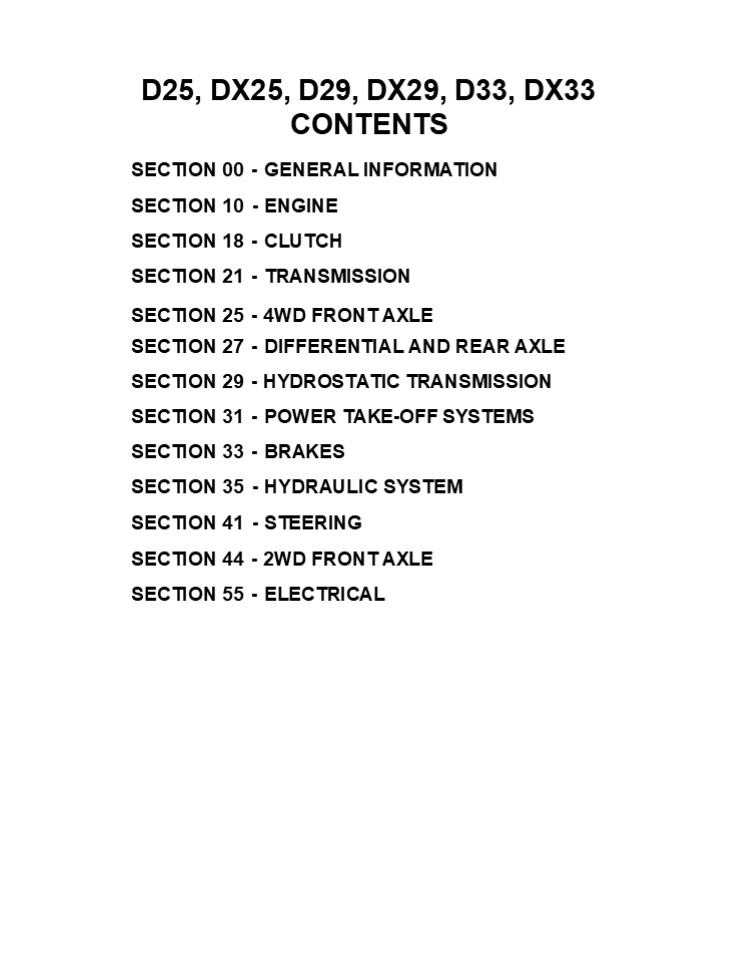
D25, DX25, D29, DX29, D33, DX33 CONTENTS
- SECTION 00 - GENERAL INFORMATION SECTION 10 -
ENGINE - SECTION 18 - CLUTCH SECTION 21 - TRANSMISSION
- SECTION 25 - 4WD FRONT AXLE
- SECTION 27 - DIFFERENTIAL AND REAR AXLE SECTION
29 - HYDROSTATIC TRANSMISSION SECTION 31 - POWER
TAKE-OFF SYSTEMS SECTION 33 - BRAKES - SECTION 35 - HYDRAULIC SYSTEM SECTION 41 -
STEERING - SECTION 44 - 2WD FRONT AXLE SECTION 55 -
ELECTRICAL
2
SECTION 00 - GENERAL INFORMATION Chapter 1 -
General Information CONTENTS
Description Page Introduction ....................
............................................
00-2 Precautionary Statements ....................
................................ 00-3 Technical
Information ......................................
.................. 00-4 Safety Precautions
..................................................
........ 00-5 Safety Decals - DX25, DX29, DX33
............................................
00-8 Instruction Decals - DX25, DX29, DX33
........................................
00-9 Safety Decals - D25, D29, D33
...............................................
00-10 Instruction Decals - D25, D29, D33
...........................................
00-11 International Symbols ......................
.................................
00-15 Specifications - D25, D29, D33
...............................................
00-16 General Dimensions - D25, D29, D33
.........................................
00-22 Specifications - DX25, DX29, DX33
...........................................
00-25 General Dimensions - DX25, DX29, DX33
.....................................
00-31 Minimum Hardware Tightening Torques
....................................... 00-34
Special Tools ....................................
.......................... 00-36 Recommended
Lubricants .......................................
............ 00-37 Tire Inflation Pressure -
Adjustments ......................................
.... 00-38 Pre-Season and Pre-Delivery Checklist
....................................... 00-39
Section
3
SECTION 00 - GENERAL INFORMATION INTRODUCTION
This repair manual provides the technical
informa- tion needed to properly service the Case
IH D25, DX25, D29, DX29, D33 and DX33 tractors.
Use this manual in conjunction with the
operator's manual for complete operation,
adjustment, and maintenance information.
On Case IH equipment, left and right are
determined by standing behind the unit, looking
in the direction of travel.
4
https//www.ebooklibonline.com Hello dear
friend! Thank you very much for reading. Enter
the link into your browser. The full manual is
available for immediate download. https//www.ebo
oklibonline.com
5
SECTION 00 - GENERAL INFORMATION PRECAUTIONARY
STATEMENTS PERSONAL SAFETY Throughout this manual
and on machine decals, you will find
precautionary statements (DANGER, WARNING,
and CAUTION) followed by specific instructions.
These precautions are intended for the personal
safety of you and those working with you. Please
take the time to read them. DANGER This word
DANGER indicates an immediate hazardous
situation that, if not avoided, will result in
death or serious injury. The color associated
with Danger is RED. WARNING This word WARNING
indicates a potentially hazardous situation that,
if not avoided, could result in death or serious
injury. The color associated with Warning is
ORANGE. CAUTION This word CAUTION indicates a
potentially hazardous situation that, if not
avoided, may result in minor or moderate injury.
It may also used to alert against unsafe
practices. The color associated with Caution is
YELLOW. FAILURE TO FOLLOW THE DANGER,
WARNING, AND CAUTION INSTRUCTIONS MAY RESULT
IN SERIOUS BODILY INJURY OR DEATH.
MACHINE SAFETY The precautionary statement
(IMPORTANT) is followed by specific
instructions. This statement is intended for
machine safety. IMPORTANT The word
IMPORTANTis used to inform the reader of
something he needs to know to prevent minor
machine damage if a certain procedure is mol
followed. INFORMATION NOTE Instructions used
to identify and present supplementary information.
6
SECTION 00 - GENERAL INFORMATION TECHNICAL
INFORMATION HARDWARE
GENERAL The D25, DX25, D29, DX29, D33 and DX33
tractors have been built using metric hardware.
Approximately 90 of the torque applied during
assembly goes to overcoming friction between the
parts. The other 10 is used to tension (stretch)
the bolt. After assembly, the frictional forces
disappear, which is the basis for the saying If
it does not fail during assembly, it will not
fail in service." The bolt may later fail due to
other factors, but not from being over tightened.
NOTE Be sure to use the hardware specified when
using tapped holes, as trying to install a metric
bolt in an inch thread, or an inch bolt in a
metric thread, will damage the thread. Certain
hardware must be tightened to specific torque
specifications. If specific torque specifications
are not noted, tighten the hardware to the
standard torque chart specification listed in
this manual.
LOCKNUTS Most locknuts are coated with a special
lubricant that is dry to the touch. Anytime a
locknut is used, a lower than normal torque is
required. Refer to the torque charts in this
manual for specific values.
PLATING Hardware used on balers is plated with
zinc chromate (gold color). Gold colored hardware
has different torquing requirements from unplated
or zinc plated (silver color) hardware because of
the difference in the coefficient of friction of
the plating material. The torque charts in this
manual list the correct specifications for gold,
silver, and unplated bolts.
JAM NUTS When using a jam nut to lock a regular
nut, the jam nut should be installed first and
tightened to one half the recommended torque,
then held in place while installing a regular nut
to the recommended torque.
THREAD LUBRICATION The addition of antiseize
compound, Molykote, oil, graphite, or any other
lubricant to a bolt decreases the friction
between it and a nut. This makes it necessary to
reduce the recommended torque to prevent over
tensioning of the bolt. When using the torque
charts in this manual, decrease the value by 20
whenever a lubricant is used.
NUT TIGHTENING Whenever possible, the nut should
be tightened, not the head of the bolt. When
tightening using the bolt head, the clamp load
can be lost because some of the torque applied
twists the bolt instead of tensioning
(stretching) it. The tension on the bolt is what
holds the joint together.
7
SECTION 00 - GENERAL INFORMATION
SAFETY PRECAUTIONS
A careful operator is the best operator. Most
accidents can be avoided by observing certain
precautions. To help prevent accidents, read and
take the following precautions before operating
this tractor. Equipment should be operated only
by those who are responsible and instructed to do
so.
- satisfactory condition to ensure your safety and
comply with legal requirements. - Keep open flame or cold weather starting aids
away from the battery to prevent fires or
explosions. Use jumper cables according to
instructions to prevent sparks which could cause
explosion. - Stop the engine before performing any service on
the tractor. - Escaping hydraulic/diesel fluid under pressure
can penetrate the skin causing serious injury.
If fluid is injected into the skin, obtain
medical attention immediately or gangrene may
result.
THE TRACTOR
- Read the Operator's Manual carefully before using
the tractor. Lack of operating knowledge can lead
to accidents. - Use an approved roll bar and seat belt for safe
operation. Overturning a tractor without a roll
bar can result in death or injury. If your
tractor is not equipped with a roll bar and seat
belt, see your Dealer for needed installation. - Always use the seat belt. The only instance when
the seat belt should not be used is if the roll
bar has been removed from the tractor. - If a front end loader is to be installed, always
use a FOPS (Falling Object Protective Structure)
canopy to avoid injury from falling objects. - Use the handholds and step plates when getting
on and off the tractor to prevent falls. Keep
steps and platform cleared of mud and debris. - Do not permit anyone but the operator to ride on
the tractor. There is no safe place for extra
riders. - Keep all safety decals clean of dirt and grime,
and replace all missing, illegible, or damaged
safety decals. See the list of decals in the
Decal section of this manual.
- DO NOT use your hand to check for leaks. Use a
piece of cardboard or paper to search for leaks. - Stop the engine and relieve pressure before
connecting or disconnecting lines. - Tighten all connections before starting the
engine or pressurizing lines.
7.
- Do not modify or permit anyone else to modify or
alter this tractor or any of its components or
functions without first consulting a Dealer. - The fuel oil in the injection system is under
high pressure and can penetrate the skin.
Unqualified persons should not remove or attempt
to adjust a pump, injector, nozzle, or any other
part of the fuel injection system. Failure to
follow these instructions can result in serious
injury. - Continuous long-term contact with used engine
oil may cause skin cancer. Avoid prolonged
contact with used engine oil. Wash skin promptly
with soap and water.
SERVICING THE TRACTOR
10. Some components of your tractor, such as
gaskets and friction surfaces (brake linings,
clutch linings, etc.) may contain asbestos.
Breathing asbestos dust is dangerous to your
health. You are advised to have any mainte- nance
or repair on such components carried out by an
authorized Dealer. However, if service operations
are to be undertaken on parts that contain
asbestos, the essential precautions listed below
must be observed
- The cooling system operates under pressure which
is controlled by the radiator cap. It is
dangerous to remove the cap while the system is
hot. Always turn the cap slowly to the first stop
and allow pressure to escape before removing the
cap entirely. - Keep any type of open flame away from the
tractor and do not smoke while refueling. Wait
for the engine to cool before refueling. - Keep the tractor and equipment, particularly
brakes and steering, maintained in a reliable and
8
SECTION 00 - GENERAL INFORMATION
- Dust found on the tractor or produced during
work on the tractor should be removed by
extraction, not by blowing. - Dust waste should be dampened, placed in a
sealed container, and marked to ensure safe
disposal. - If any cutting, drilling, etc. is attempted on
materials containing asbestos, the item should
be dampened and only hand tools or low speed
power tools used.
- mounted and will disconnect safely in case of
accidental detachment of implement. - Do not leave equipment in the raised position.
- Use the flasher/turn signal lights and SMV signs
when traveling on public roads both day and
night (unless prohibited by law). - When operating at night, adjust lights to
prevent blinding oncoming drivers. - DRIVING THE TRACTOR
OPERATING THE TRACTOR
- Watch where you are going, especially at row
ends, on roads, around trees and low hanging
obstacles. - To avoid upsets, drive the tractor with care and
at a safe speed. Use extra caution when
operating over rough ground, when crossing
ditches or slopes, and when turning corners. - To provide two-wheel braking, lock tractor brake
pedals together when transporting on roads. - Do not coast or free wheel down hills. Use the
same gear when going downhill as is used when
going uphill. - Any towed vehicle with a total weight exceeding
that of the towing tractor should be equipped
with brakes for safe operation. - If the tractor becomes stuck or the tires become
frozen to the ground, back up the tractor to
prevent upset. - Always check overhead clearance, especially when
transporting the tractor. - When operating at night, adjust lights to
prevent blinding oncoming drivers.
- Before starting the tractor, apply the parking
brake, place the PTO lever in the OFF
position, the lift control lever in the down
position, the remote control valve levers in the
neutral position, and the transmission in
neutral. - Always sit in the tractor seat when starting the
engine or operating controls. Do not start the
engine or operate controls while standing beside
the tractor. - Do not bypass the neutral start switches. Consult
your Dealer if your neutral start controls
malfunction. Use jumper cables only in the
recommended manner. Improper use can result in
tractor runaway. - Avoid accidental contact with the gear shift
lever while the engine is running, as this can
cause unexpected tractor movement. - Before getting off the tractor, disengage the
PTO, turn the engine off, and apply the parking
brake. Never get off the tractor while it is in
motion. - Do not park the tractor on a steep incline.
- Do not operate the tractor engine in an enclosed
building without adequate ventilation. Exhaust
fumes can cause death or illness. - If the power steering or engine ceases operating,
stop the tractor immediately. - Pull only from the drawbar or the lower link
drawbar in the down position. Use only a drawbar
pin that locks in place. Pulling from the tractor
rear axle or any point above the axle may cause
the tractor to upset.
OPERATING THE PTO
- When operating PTO driven equipment, shut off
the engine and wait until the PTO stops before
getting off the tractor and disconnecting the
equipment. - Do not wear loose clothing when operating the
power take-off or when near rotating equipment. - When operating stationary PTO driven equip-
ment, always place both gear shift levers in
neutral, apply the tractor parking brake, and
block the rear wheels front and back. - To avoid injury, do not clean, adjust, unclog, or
service PTO driven equipment when the tractor
engine is running. - Ensure the PTO master shield is installed at all
times. Always replace the PTO shield cap when
the PTO is not in use.
- If the front end of the tractor tends to rise
when heavy implements are attached to the three-
point hitch, install front end or front wheel
weights. Do not operate the tractor with a light
front end. - Always set the hydraulic selector lever in
position control when attaching or transporting
equip- ment. Ensure hydraulic couplers are
properly
9
SECTION 00 - GENERAL INFORMATION
SAFETY FRAME (ROPS) Your tractor is equipped with
a safety frame. It must be maintained in a
serviceable condition. Be careful when driving
through doorways or working in confined spaces
with low headroom. UNDER NO CIRCUMSTANCES should
you
DIESEL FUEL
- 1. UNDER NO CIRCUMSTANCES should gaso- line,
alcohol, or blended fuels be added to diesel
fuel. These combinations can create an increased
fire or explosive hazard. Such blends are more
explosive than pure gasoline in a closed
container such as a fuel tank. DO NOT USE THESE
BLENDS. - Never remove the fuel cap or refuel with the
engine running or hot. - Do not smoke while refueling or when standing
near fuel. - Maintain control of the fuel filler pipe nozzle
when filling the tank. - Do not fill the fuel tank to capacity. Allow room
for expansion. - Wipe up spilled fuel immediately.
- Always tighten the fuel tank cap securely.
- If the original fuel tank cap is lost, replace it
with a Case IH approved cap. A non-approved,
proprietary cap may not be safe. - Keep equipment clean and properly maintained.
- modify, drill, or alter the safety frame in any
way. Doing so may render you liable to legal
prosecu- tion. Doing so may weaken the structure
and en- danger your safety. - attempt to straighten or weld any part of the
main frame or retaining brackets which have
suffered damage. Doing so may weaken the
structure and endanger your safety. - secure any parts on the main frame or attach
your safety frame with anything other than the
special high tensile bolts and nuts specified. - attach chains or ropes to the main frame for
pull- ing purposes. - take unnecessary risks even though your safety
frame affords you the maximum protection pos-
sible.
2.
- Do not drive equipment near open fires.
- Never use fuel for cleaning purposes.
- Arrange fuel purchases so that winter grade fuels
are not held over and used in the spring.
WHEN YOU SEE THIS SYMBOL IT MEANS ATTENTION! B
ECOME ALERT! YOUR SAFETY IS INVOLVED!
10
SECTION 10 - ENGINE Chapter 1 - Engine CONTENTS
Description Page Specifications
..................................................
............. 10-2 Metric Bolt Torque
Specifications ...................................
.......... 10-10 Special Tools ...................
...........................................
10-11 Description of Operation ...................
.................................
10-12 Troubleshooting ............................
................................ 10-13 General
Information ......................................
.................. 10-19 Engine Overhaul
..................................................
......... 10-23 Disassembly, Inspection, Fits,
Clearances, and Assembly of Component Assemblies
..................................................
10-33 Engine Reassembly .........................
............................... 10-52 Engine
Lubrication System ...............................
................... 10-62 Cooling System
..................................................
.......... 10-69 Cooling System Overhaul
..................................................
. 10-73
Section
11
SECTION 10 - ENGINE - CHAPTER 1 SPECIFICATIONS
GENERAL D25 / DX25 D29 / DX29D D33/ DX33D
Net Engine DIN in Kw (Hp) 18.3 (24.5) 21.3 (28.6) 24.0 (32.3)
Gross Engine in Kw (Hp) 18.7 (25.0) 21.6 (29.0) 24.6 (33.0)
PTO in Kw (Hp) w/9 x 3 w/HST 16.2 (21.7) 15.1 (20.3) 18.7 (25.1) 17.6 (23.6) 21.7 (29.1) 20.1 (26.9)
Engine Model J843 J843 N843
Number of Cylinders 3 3 3
Bore x Stroke in mm (in.) 84 x 80 (3.31 x 3.15) 84 x 80 (3.31 x 3.15) 84 x 90 (3.31 x 3.54)
Displacement in L(in.3) 1.33 (81.2) 1.33 (81.2) 1.50 (91.3)
Compression Ratio 231 231 22.51
Rated Speed in rpm 2600 2800 2800
Muffles Location Under Hood Under Hood Under Hood
Firing Order 1-2-3 1-2-3 1-2-3
Low Idle Speed rpm 1000 1000 1000
High Idle Speed rpm 2840 3040 3040
Cylinder Arrangement In-line Vertical In-line Vertical In-line Vertical
Valve Arrangement Overhead Overhead Overhead
CYLINDER BLOCK D25 / DX25D D29 / DX29D D33/ DX33D
Bore Standard in mm (in.) 84 - 84.019 84 - 84.019 84 - 84.019
Bore Standard in mm (in.) (3.307 - 3.308) (3.307 - 3.308) (3.307 - 3.308)
Bore Maximum in mm (in.) 85.2 (3.354) 85.2 (3.354) 85.2 (3.354)
Head Surface Warp Standard in mm (in.) 0.05 (0.002) 0.05 (0.002) 0.05 (0.002)
Head Surface Warp Maximum in mm (in.) .12 (0.005) 0.12 (0.005) 0.12 (0.005)
Re-Bore Size mm (in.)
Oversize
0.5 mm (0.02 in) 84.2 - 84.7 84.2 - 84.7 84.5 - 84.519
(3.315 - 3.334) (3.315 - 3.334) (3.327 - 3.328)
1.0 mm (0.04 in) 82.7 - 83.2 82.7 - 83.2 85.0 - 85.019
(3.334 - 3.354) (3.334 - 3.354) (3.346 - 3.347)
12
SECTION 10 - ENGINE - CHAPTER 1
CYLINDER HEAD D25 / DX25 D29 / DX29 D33/ DX33
Head Ward in mm (in.) Standard Maximum 0.05 (0.002) 0.12 (0.005) 0.05 (0.002) 0.12 (0.005) 0.05 (0.002) 0.12 (0.005)
Valve Seat Width in mm (in.)
Standard
1.2 - 1.8 1.2 - 1.8 1.2 - 1.8
Maximum (0.063 - 0.071) (0.063 - 0.071) (0.063 - 0.071)
2.5 (0.098) 2.5 (0.098) 2.5 (0.098)
PISTON D25 / DX25 D29 / DX29 D33/ DX33
Valve Seat Sink in mm (in.)
Standard
0.85 - 1.15 0.85 - 1.15 0.85 - 1.15
Maximum (0.0334 - 0.0453) (0.0334 - 0.0453) (0.0334 - 0.0453)
1.8 (0.071) 1.8 (0.071) 1.8 (0.071)
Valve Angle 45_
Diameter in mm (in.)
Standard 83.913 - 83.928
(3.303 - 3.304) 83.948 - 83.963 83.948 - 83.963
Minimum 83.7 (3.295) (3.3050 - 3.3056) (3.3050 - 3.3056)
83.7 (3.2593) 83.7 (3.2593)
Bore Clearance in mm (in.)
Standard
0.088 - 0.106 0.088 - 0.106 0.088 - 0.106
Maximum (0.0034 - 0.0041) (0.0034 - 0.0041) (0.0034 - 0.0041)
0.3 (0.0118) 0.3 (0.0118) 0.3 (0.0118)
Piston Pin Bore in mm (in.) 24.999 - 25.003 (0.984 - 0.9843) 25.0 (0.0985) 27.999 - 28.003 (1.10231 - 1.1025) 28.02 (1.1031)
Standard 24.999 - 25.003 (0.984 - 0.9843) 25.0 (0.0985) 27.999 - 28.003 (1.10231 - 1.1025) 28.02 (1.1031)
24.999 - 25.003 24.999 - 25.003 (0.984 - 0.9843) 25.0 (0.0985) 27.999 - 28.003 (1.10231 - 1.1025) 28.02 (1.1031)
Maximum (0.984 - 0.9843) 24.999 - 25.003 (0.984 - 0.9843) 25.0 (0.0985) 27.999 - 28.003 (1.10231 - 1.1025) 28.02 (1.1031)
25.0 (0.0985) 24.999 - 25.003 (0.984 - 0.9843) 25.0 (0.0985) 27.999 - 28.003 (1.10231 - 1.1025) 28.02 (1.1031)
Piston Pin Clearances in mm
(in.)
Standard - 0.001 0.007 (0 - 0.0002) -0.001 0.007 (0 - 0.0002) -0.002 0.008 (-0.00008 0.0003)
Maximum 0.02 (0.0008) 0.02 (0.0008) 0.02 (0.0008)
Available Oversized in mm (in.) 0.5 and 1.0 (0.20 and 0.40)
13
SECTION 10 - ENGINE - CHAPTER 1
MODEL J843
MODEL N843
4
MODEL J843
MODEL N843
5
14
- SECTION 10 - ENGINE - CHAPTER 1
- SEPARATING THE TRACTOR BETWEEN THE ENGINE AND
CLUTCH HOUSING - REMOVAL
- NOTE Place jack stands as support under clutch
housing. - Open the hood and remove the side panels.
- Disconnect the battery ground cable.
- With hydrostatic transmission, remove the HST
pedal, 1.
6
4. Remove the differential lock pedal, 1.
7
- Remove the floor mat, 1.
- Remove the seat, 2.
- If equipped, remove the loader control valve
mounts, and the valve, 3. - Remove the knobs from the controls on both
fenders. - Remove the roll bar, 4.
4
8
15
SECTION 10 - ENGINE - CHAPTER 1 10. Remove the
parking brake handle, 1.
9
11. Disconnect the power steering tubing, 1, from
the steering motor. Cap and plug all openings.
10
- Remove the steering wheel, 1.
- Remove the instrument panel, 2, and unplug the
wire harness.
11
16
SECTION 10 - ENGINE - CHAPTER 1
- Disconnect the throttle control cable, 1, from
the injection pump. - Remove the fuel hose, 2, from the fuel shutoff
valve, 3, and filter and drain the fuel into a
clean container. Cap and plug all openings. - Remove the fuel tank bracket and remove the fuel
tank.
i s
O
- Remove the right and left fender hardware and
remove the fenders. - Remove the step plate.
attaching
- Drain the transmission fluid container.
- Remove the hydraulic suction
into a clean
12
tube, system
- pressure tube, and fluid return line from the
tractor. - With hydrostatic transmission, remove the
hydraulic lines at the filter and cooler. - With FWD, remove the FWD drive shaft, discussed
in Driveline - Section 23. - Drain the engine oil in a clean container and
remove the oil filter. - Disconnect the starter wiring harness, 1, and
remove the starter attaching hardware, 2, and
remove the starter.
13
17
- SECTION 10 - ENGINE - CHAPTER 1
- Remove the air cleaner, 1.
- Attach a hoist chain to the engine lift hook,
located on the left rear of the engine. - Remove the engine to clutch housing buckle up
bolts and carefully separate the engine from the
clutch housing.
14
INSTALLATION Installation generally follows the
removal procedures in reverse order. During
installation coat the engine and clutch housing
mating surfaces with liquid sealer. Use caution
to prevent excess sealer from entering the inside
of the housing and contaminating the hydraulic
fluid supply.
18
SECTION 10 - ENGINE - CHAPTER 1 ENGINE
OVERHAUL ENGINE DISASSEMBLY 1. Turn coolant tap
bolt, 1, counterclockwise to drain fluid. Remove
the radiator assembly. See Radiator Removal,
discussed later in this section.
15
2. Remove the air cleaner assembly, 1, along with
the air cleaner hoses. Push in on assembly, 1,
and turn counterclockwise to remove.
16
3. Remove bolts, 1, for final removal of air
cleaner assembly.
17
19
SECTION 10 - ENGINE - CHAPTER 1
4. Remove the exhaust muffles, 1, and manifold
assembly, 2. Loosen bolt, 3, and bolt, 4, Figure
19, to remove exhaust muffler. Loosen six bolts,
5, to remove exhaust manifold.
HOT
18
19988039
19
- FUEL INJECTOR AND GLOW PLUG REMOVAL
- Clean all dirt and oil from the injectors and
surrounding areas. - Disconnect the fuel lines, 1, from the injectors
and cap all openings. - Remove the injector fuel leak-off line, 3.
- Remove the injector assemblies, 2.
- Remove the glow plug bus connector, 5, and
remove the glow plugs, 4.
20
20
SECTION 10 - ENGINE - CHAPTER 1 OIL PRESSURE
SWITCH Remove the oil pressure switch, 1.
21
- TEMPERATURE SENDING SWITCH AND ALTERNATOR REMOVAL
- Remove the temperature sending switch, 1, from
the front of the cylinder head. - Loosen the alternator mounting bolts, 2, and
remove the V-belt, 3, from the drive pulley. - Disconnect the alternator wires from the back of
alternator, 4. - Remove the alternator mounting bolts, 2, and
remove the alternator.
22
- FAN, WATER PUMP, AND EXTERNAL OIL TUBE REMOVAL
- Remove the fan and water pump assembly. See Fan
Removal and Water Pump Removal discussed later
in this section. - Remove the external oil transfer tube banjo
bolt, 1, from the front of the cylinder head.
19988040
23
21
SECTION 10 - ENGINE - CHAPTER 1 AIR INLET
MANIFOLD REMOVAL Remove the six retaining bolts,
1, and remove the air inlet manifold assembly, 2.
24
VALVE COVER REMOVAL Loosen the three bolts, 1, to
remove the valve cover, 2.
25
ROCKER ARM SHAFT AND SUPPORT BRACKET
REMOVAL Remove the rocker arm shaft and support
bracket as an assembly, 1. NOTE Alternately
loosen the rocker support bolts a turn at a time
to prevent distorting the rocker shaft.
26
22
- SECTION 10 - ENGINE - CHAPTER 1
- CYLINDER HEAD REMOVAL
- Remove the valve stem caps, 1, and push rods,
- 2.
- NOTE Keep all valve components in separately
marked containers for re- assembly in their
original location. - To remove the cylinder head, remove the cylinder
head bolts, 3, by alternately loosening a half
turn at a time to prevent warping the head.
27
VALVE TAPPET REMOVAL Remove the valve tappets, 1,
from the machined bore in the cylinder block.
28
FUEL SHUTOFF SOLENOID REMOVAL Remove the wire
connector and unscrew the fuel shutoff solenoid,
1.
29
23
SECTION 10 - ENGINE - CHAPTER 1 ENGINE TIMING
GEAR COVER, TIMING GEARS, AND CAM SHAFT Timing
Gear Cover Removal
- Drain the engine crankcase oil.
- Remove the crankshaft pulley.
- Disconnect the throttle control rod at the
injection pump. - Loosen the four injection pump mounting bolts, 2,
and raise the injection pump, 3, enough to remove
the spring pin, 1, and separate the governor link
from the control rack. Remove the injection pump.
2
4.
30
5. Remove the power steering pump reservoir tank
dipstick-filler cap, 2.
31
6. Remove the reservoir drain plug, 3, and drain
the hydraulic fluid out of the reservoir tank, 1,
into a suitable container.
19988041
32
24
SECTION 10 - ENGINE - CHAPTER 1
7.
- Loosen the hose clamp, 2, on the suction tube, 3,
and remove the suction hose from the steering
pump, 5. - Remove the pressure tube, 1, from the bottom of
- the steering pump.
- Remove the through bolts, 4, and remove the
steering pump from the front cover. Cap the lines
and pump openings.
19988042
33
10. Remove retaining nut and washer, 1. Pull
crankshaft pulley, 2, off of crankshaft, 3.
34
11. Remove the retaining bolts, 1, and lift the
cover, 2, off the locating dowels.
35
25
SECTION 10 - ENGINE - CHAPTER 1 Timing Gears and
Camshaft Removal 1. Remove retaining ring, 1, and
remove the idler gear, 3, and oil pump assembly,
2.
36
- Remove the two bolts, 1, securing the keeper
plate, 3. One must be accessed using the access
hole, 2, in the cam gear. - Slide the camshaft and gear out of the camshaft
bore.
37
- Oil Sump Removal
- Remove the oil sump retainer bolts, 1.
- Remove the oil sump and discard gasket.
38
26
- SECTION 10 - ENGINE - CHAPTER 1
- Oil Suction Pipe and Strainer Removal
- Remove the two retaining bolts, 1.
- Remove the oil strainer, 2, and rotate the oil
suction pipe, 3, out of its bore. Remove from the
front side of the block.
39
- Connecting Rods, Bearings, and Pistons, Rings
Removal - Remove the two bolts, 1, retaining the
connecting rod caps, 2. - Remove the connecting rod caps and lower half of
connecting rod bearing. - If necessary, remove any ridge from the top of
the cylinder bores using a suitable ridge reamer.
40
- Push the piston and connecting rod out of the
cylinder block. - Replace the connecting rod cap to the piston
assembly it was removed from. Keep together in
cylinder sequence.
41
27
SECTION 10 - ENGINE - CHAPTER 1
- Flywheel Removal
- Loosen the flywheel retaining bolts.
- Using a brass drift and hammer, tap the end of
the crankshaft, 1, to loosen the flywheel, 2,
from the shaft.
42
- Backplate and Oil Seal
- Remove the backplate retaining bolts and remove
the backplate. - Remove the rear oil seal, 1.
43
- Crankshaft and Main Bearings Removal
- Remove the crankshaft bearing holder retaining
bolts, 1. - Slide the crankshaft and main bearing assembly
through the rear of the engine.
44
28
Suggest If the above button click is invalid.
Please download this document first, and then
click the above link to download the complete
manual. Thank you so much for reading
29
- SECTION 10 - ENGINE - CHAPTER 1
- DISASSEMBLY, INSPECTION, FITS, CLEARANCES, AND
ASSEMBLY OF COMPONENT ASSEMBLIES - CYLINDER HEAD DISASSEMBLY
- Clean the cylinder head and remove any carbon
deposits from around the valve heads. - Use a valve spring compressor and remove the
valve spring retainer locks, 1, spring, 2, and
spring retainer, 3, from each valve, 4. - Remove the valves and place the valve components
together in separately marked containers for
reassembly in their original position. - 45
- CYLINDER HEAD INSPECTION AND
- REPAIR
- Clean all carbon deposits from the combustion
chamber and valve ports using a wire brush and
scraper. - Clean all dirt and residue from the gasket
surface using care not to scratch or nick the
machined surface. - Clean the cylinder head in solvent and air dry.
- Inspect the head for cracks or damage in the
following areas - Valve ports
- Valve seats, 2
- Inspect the gasket surfaces for scratches or
nicks, which could cause leakage. - Examine the core hole plugs for rust or signs of
leakage. If a plug shows signs of damaging rust
or leakage, replace all plugs in the head. - Inspect the prechamber for carbon deposits and
looseness. Remove any carbon deposits found. If
prechamber is found to be loose, cylinder head
may be warped.
46
10-33
30
https//www.ebooklibonline.com Hello dear
friend! Thank you very much for reading. Enter
the link into your browser. The full manual is
available for immediate download. https//www.ebo
oklibonline.com
Recommended
CrystalGraphics Presentations


