
CASE IH JX80 Tractor Service Repair Manual Instant Download (1)
Title:
CASE IH JX80 Tractor Service Repair Manual Instant Download (1)
Description:
CASE IH JX80 Tractor Service Repair Manual Instant Download (1) –
Number of Views:0
Title: CASE IH JX80 Tractor Service Repair Manual Instant Download (1)
1
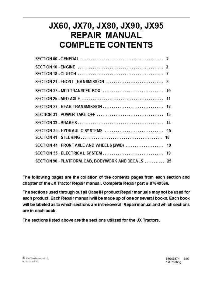
JX60, JX70, JX80, JX90, JX95 REPAIR MANUAL
COMPLETE CONTENTS
SECTION 00 - GENERAL .............................
............... 2 SECTION 10 - ENGINE
..............................................
2 SECTION 18 - CLUTCH ............................
.................. 7 SECTION 21 - FRONT
TRANSMISSION ...............................
8 SECTION 23 - MFD TRANSFER BOX
................................. 10 SECTION 25 -
MFD AXLE .........................................
... 11 SECTION 27 - REAR TRANSMISSION
................................. 12 SECTION 31 -
POWER TAKE-OFF ...................................
. 13 SECTION 33 - BRAKES .........................
..................... 14 SECTION 35 - HYDRAULIC
SYSTEMS ................................
15 SECTION 41 - STEERING .........................
................... 18 SECTION 44 - FRONT AXLE
AND WHEELS (2WD) ..................... 19 SECTION
55 - ELECTRICAL SYSTEM ...........................
...... 19 SECTION 90 - PLATFORM, CAB, BODYWORK
AND DECALS ........... 25 The following pages
are the collation of the contents pages from each
section and chapter of the JX Tractor Repair
manual. Complete Repair part 87649366. The
sections used through out all Case IH product
Repair manuals may not be used for each product.
Each Repair manual will be made up of one or
several books. Each book will be labeled as to
which sections are in the overall Repair manual
and which sections are in each book. The
sections listed above are the sections utilized
for the JX Tractors.
? 2007 CNH America LLC Printed In U.S.A.
87649371 3/07 1st Printing
2
SECTION 00 - GENERAL - CHAPTER 1
1
SECTION 00 - GENERAL Chapter 1 -
General CONTENTS
Description Page General Instructions
..................................................
.......... 3 Health and Safety ...................
...........................................
5 Precautionary Statements .......................
.............................. 15 Safety
..................................................
.................... 16 Ecology and the
Environment ......................................
............ 19 Minimum Hardware Tightening
Torques .........................................
20 Federal Emissions Warranty ...................
................................ 22 California
Emission Control Warranty Statement
.................................. 23
Consumables ......................................
.......................... 25
Section
3
SECTION 00 - GENERAL - CHAPTER 1 WARNING WARNING
2
All maintenance and repair work described in
this manual must be performed exclusively by
CASE IH service technicians in strict accordance
with the instructions given and using any
specific tools necessary.
The Manufacturer and all organizations belong-
ing to the Manufacturers distribution network,
including but not restricted to national,
regional or local distributors, will accept no
responsibility for personal injury or damage to
property caused by abnormal function of parts
and/or compo- nents not approved by the
Manufacturer, including those used for
maintenance and/or repair of the product
manufactured or marketed by the Manufacturer. In
any case, the product manufactured or marketed
by the Manufacturer is covered by no guarantee
of any kind against personal injury or damage to
property caused by abnormal function of parts
and/or components not approved by the
Manufacturer.
WARNING
Anyone who performs the operations described
herein without strictly following the
instructions is personally responsible for
resulting injury or damage to property.
4
https//www.ebooklibonline.com Hello dear
friend! Thank you very much for reading. Enter
the link into your browser. The full manual is
available for immediate download. https//www.eb
ooklibonline.com
5
SECTION 00 - GENERAL - CHAPTER 1
3
GENERAL INSTRUCTIONS
IMPORTANT NOTICE All maintenance and repair
operations described in this manual should be
carried out exclusively by the authorized
workshops. All instructions detailed should be
carefully observed and special equipment
indicated should be used if necessary. Everyone
who carries out service operations described
without carefully observing these direc- tives
will be directly responsible for resulting
consequences.
- Take care to insert the seal perpendicular to its
seat while you are pressing it. Once the seal is
settled, ensure that it contacts the thrust
element, if required - To prevent damaging the sealing lip against the
shaft, place a suitable protection during
installation.
O RINGS Lubricate the O rings before inserting
them into their seats. This will prevent the O
rings from roll over and twisting during
mounting, which will jeopardize sealing.
SHIMMING At each adjustment, select adjusting
shims, measure them individually using a
micrometer and then sum up recorded values. Do
not rely on measuring the whole shimming set,
which may be incorrect, or on the rated value
indicated for each shim.
SEALERS Apply silicone/gasket eliminator over the
mating surfaces marked with an X. Before
applying the sealer, prepare the surface as
follows
ROTATING SHAFT SEALS To correctly install
rotating shaft seals, observe the following
instructions
- remove possible scales using a metal brush
- thoroughly degrease the surfaces using one of
the following cleaning agents trichlorethylene,
diesel fuel or a water and soda solution.
- Let the seal soak into the same oil as it will
seal for at least half an hour before mounting - Thoroughly clean the shaft and ensure that the
shaft working surface is not damaged - Place the sealing lip towards the fluid. In case
of a hydrodynamic lip, consider the shaft
rotation direction and orient grooves in order
that they deviate the fluid towards the inner
side of the seal - Coat the sealing lip with a thin layer of
lubricant (oil rather than grease) and fill the
gap between the sealing lip and the dust lip of
double lip seals with grease - Insert the seal into its seat and press it down
using a flat punch. Do not tap the seal with a
hammer or a drift
BEARINGS It is advisable to heat the bearings to
80? to 90?C (176? to 194?F) before mounting them
on their shafts and cool them down before
inserting them into their seats with external
tapping.
SPRING PINS When mounting split socket spring
pins, ensure that the pin notch is oriented in
the direction of the effort to stress the
pin. Spiral spring pins should not be oriented
during installation.
6
SECTION 00 - GENERAL - CHAPTER 1
4
- GENERAL INSTRUCTIONS
- PRECAUTIONARY NOTICE
- Only authorized workshops should carry out
maintenance and repair operations on the tractor,
or tractor compo- nents. Carefully observe all
instructions, safety precautions, and the use of
equipment such as special tools, as detailed in
this manual. Damage to the tractor, or injury to
personnel is the direct responsibility of anyone
who fails to observe these precautions. - EQUIPMENT NOTICE
- The equipment proposed in this manual is
- Designed and studied expressly for use on Case IH
tractors - Necessary for adequate and reliable repair of the
tractor - Strictly tested for the efficient and long
lasting life cycle of the tractor - SPARE PARTS NOTICE
- Genuine CASE IH spare parts guarantee the same
quality, safety and life cycle as original
components. These parts bear the logo. - GENERAL NOTICES
- In this manual, the description FRONT, REAR,
RIGHT- HAND and LEFT- HAND refer to the view
seen by the operator while in the operators
seat, looking in the direction in which the
tractor normally moves. - Wear limits detailed in this manual, although
advised, are not binding.
7
SECTION 00 - GENERAL - CHAPTER 1
5
HEALTH AND SAFETY CONTENTS Description Page HEAL
TH AND SAFETY PRECAUTIONS ........................
................................. 5 ACIDS AND
ALKALIS ..........................................
............................... 6 ADHESIVES AND
SEALERS - see Fire ...............................
.......................... 6 ANTIFREEZE - see
Fire, Solvents e.g. Isopropanol, Ethylene Glycol,
Methanol. ...................... 6 ARC WELDING -
see Welding. .....................................
............................ 7 BATTERY ACIDS -
see Acids and Alkalis. ...........................
............................ 7 BRAKE AND CLUTCH
FLUIDS (Polyalkylene Glycols) - see Fire.
................................... 7 BRAZING -
see Welding. .....................................
................................. 7 CHEMICAL
MATERIALS - GENERAL - see Legal Aspects.
........................................ 7 DOS
..................................................
..................................... 7 DO NOTS
..................................................
................................. 8 CORROSION
PROTECTION MATERIALS - see Solvents, Fire.
.................................... 8 DUSTS
..................................................
................................... 8 ELECTRIC
SHOCK ............................................
............................... 8 EXHAUST FUMES
..................................................
......................... 9 FIBER INSULATION -
see Dusts. .......................................
....................... 9 FIRE - see Welding,
Foams, Legal Aspects. ............................
......................... 9 FIRST AID
..................................................
................................ 9 FOAMS -
Polyurethane - see Fire. .........................
.................................... 9 FUELS -
see Fire, Legal Aspects, Chemicals - General,
Solvents. ................................ 10
GAS CYLINDERS - see Fire. ........................
........................................
10 GENERAL WORKSHOP TOOLS AND EQUIPMENT
............................................. 11
LEGAL ASPECTS ....................................
.......................................
11 LUBRICANTS AND GREASES ........................
........................................
11 PAINTS - see Solvents and Chemical Materials -
General. .......................................
12 SOLDER - see Welding. ........................
............................................
12 SOLVENTS - see Chemical Materials - General
Fuels (Kerosene), Fire. ..........................
. 13 SUSPENDED LOADS ............................
...........................................
13 WELDING - see Fire, Electric Shock, Gas
Cylinders. .......................................
..... 13
HEALTH AND SAFETY PRECAUTIONS Many of the
procedures associated with vehicle maintenance
and repair involve physical hazards or other
risks to health. This section lists, alphabeti-
cally, some of these hazardous operations and the
materials and equipment associated with them. The
precautions necessary to avoid these hazards are
identified. The list is not exhaustive and all
operations and procedures and the handling of
materials, should be carried out with health and
safety in mind.
8
SECTION 00 - GENERAL - CHAPTER 1
6
ACIDS AND ALKALIS -- see Battery acids, e.g.
caustic soda, sulfuric acid. Used in batteries
and cleaning materials. Irritant to the skin,
eyes, nose and throat. Causes burns.
Provide adequate ventilation and avoid skin and
eye contact. Follow manufacturers instructions.
Anaerobic, Cyanoacrylate and other Acrylic
Adhesives Many are irritant, sensitizing or
harmful to the skin. Some are eye
irritants. Skin and eye contact should be avoided
and the manufacturers instructions
followed. Cyanoacrylate adhesives (super-
glues) must not contact the skin or eyes. If
skin or eye tissue is bonded cover with a clean
moist pad and get medical attention. do not
attempt to pull tissue apart. Use in well
ventilated areas as vapors can cause irritation
of the nose and eyes. For two- pack systems see
Resin based adhesives/ sealers.
Avoid splashes to the skin, eyes and clothing.
Wear suitable protective gloves and goggles.
Can destroy ordinary protective clothing. Do not
breathe mists. Ensure access to water and soap is
readily available for splashing accidents.
ADHESIVES AND SEALERS -- see Fire Highly
Flammable and combustible. Generally should be
stored in No Smoking areas cleanliness and
tidiness in use should be observed, e.g.
disposable paper covering benches should
be dispensed from applicators where possible
contain- ers, including secondary containers,
should be labelled. Solvent based
Adhesives/Sealers - See Solvents. Follow
manufacturers instructions. Water based
Adhesives/Sealers Those based on polymer
emulsions and rubber lattices may contain small
amounts of volatile toxic and harmful chemicals.
Skin and eye contact should be avoided and
adequate ventilation provided during use. Follow
manufacturers instructions. Resin based
Adhesives/Sealers - e.g. epoxide and
formaldehyde resin based. Mixing should only be
carried out in well ventilated areas as harmful
or toxic volatile chemicals may be
released. Skin contact with uncured resins and
hardeners can result in irritation dermatitis
and absorption of toxic or harmful chemicals
through the skin. Splashes can damage the eyes.
Isocyanate (Polyurethane) Adhesives/ Sealers --
see Resin based Adhesives.
Individuals suffering from asthma or respiratory
allergies should not work with or near these
materials as sensitivity reactions can
occur. Any spraying should preferably be carried
out in exhaust ventilated booths removing vapors
and spray droplets from the breathing zone.
Individuals working with spray applications
should wear supplied air respirators.
ANTIFREEZE -- see Fire, Solvents e.g.
Isopropanol, Ethylene Glycol, Methanol. Highly
Flammable and Combustible. Used in vehicle
coolant systems, brake air pressure systems,
screenwash solutions. Vapors given off from
coolant antifreeze (glycol) arise only when
heated. Antifreeze may be absorbed through the
skin in toxic or harmful quantities. Antifreeze
if swallowed is fatal and medical attention must
be found immediately.
9
SECTION 00 - GENERAL - CHAPTER 1
7
ARC WELDING -- see Welding.
The effects of excessive exposure to chemicals
may be immediate or delayed briefly experienced
or permanent cumulative superficial life
threatening or may reduce life- expectancy.
BATTERY ACIDS -- see Acids and Alkalis. Gases
released during charging are explosive. Never
use naked flames or allow sparks near charging
or recently charged batteries.
DOS Do remove chemical materials from the skin
and clothing as soon as practicable after
soiling. Change heavily soiled clothing and
have it cleaned. Do carefully read and observe
hazard and precaution warnings given on material
containers (labels) and in any accompanying
leaflets, poster or other instructions. Material
health and safety data sheets can be obtained
from Manufacturers. Do organize work practices
and protective clothing to avoid soiling of the
skin and eyes breathing vapors/aerosols/dusts/fu
mes inadequate container labelling fire and
explosion hazards. Do wash before job breaks
before eating, smoking, drinking or using toilet
facilities when handling chemical materials. Do
keep work areas clean, uncluttered and free of
spills. Do store according to national and local
regulations. Do keep chemical materials out of
reach of children.
BRAKE AND CLUTCH FLUIDS (Polyalkylene Glycols) --
see Fire. Combustible. Splashes to the skin and
eyes are slightly irritating. Avoid skin and eye
contact as far as possible. Inhalation of vapor
hazards do not arise at ambient temperatures
because of the very low vapor pressure.
BRAZING -- see Welding.
CHEMICAL MATERIALS - GENERAL -- see Legal
Aspects. Chemical materials such as solvents,
sealers, adhesives, paints, resin foams, battery
acids, antifreeze, brake fluids, oils and grease
should always be used with caution and stored
and handled with care. They may be toxic,
harmful, corrosive, irritant or highly flammable
and give rise to hazardous fumes and dusts.
10
1
SECTION 10 - ENGINE - CHAPTER 1
SECTION 10 - ENGINE Chapter 1 - Engine CONTENTS
Description Page Specifications
..................................................
................ 2 Special Tools
..................................................
.............. 10 Tightening Torques
..................................................
......... 14 Angular Torque Data
..................................................
.... 14 Sectional Views ..........................
....................................
15 Troubleshooting ...............................
............................... 19 Overhaul
..................................................
.................. 23 Engine .....................
.............................................
23 Removal .......................................
...................... 23 Installation
..................................................
.......... 34 Disassembly ........................
.................................. 36 Assembly
..................................................
.......... 51 Rotating Counterweight Dynamic
Balancer ................................ 51
Compression Test .................................
.................... 61 Checks, Dimensions, and
Repairs ..........................................
. 62 Cylinder Block ..............................
.......................... 62 Crankshaft, Main
Bearings, and Flywheel ...........................
...... 64 Connecting Rods .......................
............................... 68 Pistons
..................................................
............. 69 Valves ..........................
..................................... 72 Tappets
..................................................
............ 72 Camshaft .........................
.................................... 73 Valve
Timing Check .....................................
............... 74 Cylinder Head
..................................................
...... 75 Rotating Counterweight Dynamic Balancer
................................ 76 Valve Guides
..................................................
....... 77 Valve Seats in Cylinder Head
...........................................
80 Crankshaft Front Oil Seal .....................
.......................... 81 Valve Clearance
..................................................
..... 87
Section
10 001 10
10 001 54
10 102 70
11
2
SECTION 10 - ENGINE - CHAPTER 1
SPECIFICATIONS
GENERAL SPECIFICATIONS 3- cylinder 4- cylinder
Engine type JX60 (BOSCH pump naturally aspirated) .................. - JX70 (BOSCH pump turbocharged) ...................... JX80 (BOSCH pump naturally aspirated) .................. - JX90 (BOSCH pump turbocharged) ...................... - JX95 (BOSCH pump turbocharged) ...................... 179 cu. in (2.9 L) 179 cu. in (2.9 L) -- -- -- -- -- 238 cu. in (3.0 L) 238 cu. in (3.0 L) 238 cu. in (3.0 L)
Cycle ................................................. Diesel, 4- stroke Diesel, 4- stroke
Fuel injection .......................................... Direct Direct
No. of in- line cylinders .................................. 3 4 3 4
Cylinder liners .......................................... dry force- fitted in cylinder block dry force- fitted in cylinder block
Piston diameter
- JX60 ................................................ 100 mm (3.937 in.) -- 100 mm (3.937 in.) --
- JX70 ................................................ 104 mm (4.094 in.) -- 104 mm (4.094 in.) --
- JX80 ................................................ -- 100 mm (3.937 in.) -- 100 mm (3.937 in.)
- JX90 ................................................ -- 104 mm (4.094 in.) -- 104 mm (4.094 in.)
- JX95 ................................................ -- 104 mm (4.094 in.) -- 104 mm (4.094 in.)
Piston stroke ........................................... 115 mm 115 mm
Total displacement
- JX60 ................................................ 2710 cm3 (165 in3) -- 2710 cm3 (165 in3) --
- JX70 ................................................ 2931 cm3 (175 in3) -- 2931 cm3 (175 in3) --
- JX80 ................................................ -- 3613 cm3 (220 in3) -- 3613 cm3 (220 in3)
- JX90 ................................................ -- 3908 cm3 (238 in3) -- 3908 cm3 (238 in3)
- JX95 ................................................ -- 3908 cm3 (238 in3) -- 3908 cm3 (238 in3)
Compression ratio ...................................... 17 to 1 naturally aspirated 16.5 to 1 turbocharged 17 to 1 naturally aspirated 16.5 to 1 turbocharged
Maximum power
- JX60 ................................................ 40.4 kW (JX60) -- 40.4 kW (JX60) --
- JX70 ................................................ 44,1 kW (JX70) -- 44,1 kW (JX70) --
- JX80 ................................................ -- 51,5 kW (JX80) -- 51,5 kW (JX80)
- JX90 ................................................ -- 58,8 kW (JX90) -- 58,8 kW (JX90)
- JX95 ................................................ -- 70 kW (JX95) -- 70 kW (JX95)
Fast idling speed ....................................... 2500 rev/min 2500 rev/min
Maximum torque (daNm) at 1500 rpm
- JX60 ................................................ 20.7 (153 ft-lb) -- 20.7 (153 ft-lb) --
- JX70 ................................................ 25.0 (184 ft-lb) -- 25.0 (184 ft-lb) --
- JX80 ................................................ -- 27.9 (206 ft-lb) -- 27.9 (206 ft-lb)
- JX90 ................................................ -- 32.0 (236 ft-lb) -- 32.0 (236 ft-lb)
- JX95 ................................................ -- 33.7 (249 ft-lb) -- 33.7 (249 ft-lb)
Number of main bearings ................................ 4 5 4 5
Sump pan ............................................. Structural, cast iron Structural, cast iron
Rev counter/hourmeter ............................
.... Operating system ...........................
............ Hour counter calibrated for engine
speed of ................
incorporated in control panel from gear on
camshaft 1800 rpm
12
3
SECTION 10 - ENGINE - CHAPTER 1
Timing System ........................................ overhead valves operated camshaft located in engine block through tappets, pushrods and rockers camshaft is driven by the crankshaft through helical gears
Intake
- start before TDC ................................... 12o
- end after BDC ...................................... 31o
Exhaust
- start before BDC ................................... 50o
- end after TDC ...................................... 16o
Valve clearance for timing check .......................... 0.45 mm (0.0177 in.)
Valve clearance for normal running (engine cold)
- intake ............................................. 0.30 ? 0.05 mm (0.01 ? 0.002 inches)
- exhaust ............................................ 0.30 ? 0.05 mm (0.01 ? 0.002 inches)
CRANKCASE/CYLINDER BLOCK DATA mm (in)
Cylinder block ............................................ Internal diameter of cylinders ............................... Maximum permissible cylinders ovality or taper due to wear (1) . Diameter of main shell bearing seats ........................ Diameter of camshaft bearing seats - front .................................................. - center ................................................ - rear ................................................... Diameter of standard tappet bores in crankcase .............. Tappet oversizes ......................................... cast-iron monobloc with parent-bore cylinders, incorporating seatings for crankshaft bearings, camshaft and pushrod/tappet assemblies 104.000 to 104.024 (4.094 - 4.095) 0.12 (0.004) 84.200 to 84.230 (3.314 - 3.316) 54.780 to 54.805 (2.156 - 2.157) 54.280 to 54.305 (2.137 - 2.138) 53.780 to 53.805 (2.117 - 2.118) 15.000 to15.018 (0.590 - 0 .591) 0.1 - 0.2 - 0.3 (0.004 - 0.007 - 0.011)
(1) Measure in the area swept by piston rings,
both parallel and perpendicular to the crankshaft
axis.
13
15
SECTION 10 - ENGINE - CHAPTER 1
SECTIONAL VIEWS
5 1
6
3
2
4
7
25357
7
Longitudinal View of 4-Cylinder Engine (JX80,
JX90 and JX95)
- Cylinder Head Bolts
- Main Bearing Cap Bolts
- Big-end Cap Bolts
- Flywheel Mounting Bolts
- Rocker Shaft Pedestal Bolts
- Crankshaft Hub Retaining Nut
- Fan and Alternator Pulley Bolts
14
16
SECTION 10 - ENGINE - CHAPTER 1
1 2 7 6 5 4 3 25355
8
- Longitudinal View of 3- Cylinder Engine (JX60
and JX70 models) - Big- end cap bolts
- Fan and alternator pulley bolts
- Crankshaft hub retaining bolts
- Rocker shaft pedestal bolts
- Cylinder head bolts
- Flywheel mounting bolts
- Main bearing cap bolts
15
23
SECTION 10 - ENGINE - CHAPTER 1
OVERHAUL
ENGINE Removal
DANGER Lift and handle all heavy parts using
suitable lifting equipment. Make sure that the
load is supported by means of suitable slings and
hooks. Make sure that no-one is standing in the
vicinity of the load to be lifted. WARNING Alwa
ys use suitable tools to align holes in parts.
NEVER USE YOUR FINGERS OR HANDS.
- Disconnect the battery negative (ground) and
positive cables (1). - Drain oil from the transmission/gearbox.
- Drain the cooling system.
1 25621
11
4. Unscrew the nut (1) from the front ballast
retaining pin.
11 TRE0601A
12
16
24
SECTION 10 - ENGINE - CHAPTER 1
5. Remove the ballast (1) from the front support.
11 TRE0602A
13
6. Remove the exhaust pipe. Attach lifting
chains to the hood (1) using tools 50131 and
50132 and attach the chain to the hoist.
1 24872
14
7. Detach the electrical leads (1) from the
headlamps (2).
1 2 24873
15
8. Detach the struts (1) from hood.
1 TRE0603A
16
17
25
SECTION 10 - ENGINE - CHAPTER 1
9. Remove the four hood hinge bolts (1) and lift
the hood clear.
11 TRE0604A
17
10. Remove the fan guard (1) from right-hand side
of the fan.
1 25028
18
11. Disconnect the tachometer cable (1) and
remove the retaining ring and sleeve.
1 25046
19
12. Detach the throttle control spring (1) and
remove the throttle lever (2).
11 22 25183
20
18
26
SECTION 10 - ENGINE - CHAPTER 1
13. Detach the cab air-conditioning pipes (1) and
(2) (if applicable).
1
2
24892
21
14. Detach the cab heating pipes (1) and (2) (if
applicable).
1 2 25411
22
15. Disconnect the main harness electrical
connectors.
1 TRE0605A
23
16. Remove the fusebox by unscrewing the nut (1)
1 TRE0606A
24
19
27
SECTION 10 - ENGINE - CHAPTER 1
17. Disconnect the delivery and return lines (1)
to the power steering cylinders.
1 TRE0607A
25
18. Remove the supply hose (1) from the lift pump.
1 TRE0608A
26
19. Detach the lift pump delivery pipe (1).
1 TRE0609A
27
20. Detach the fuel pipes from the fuel injection
pump and the pipe connecting the fuel tank to
the fuel filter (1).
1 TRE0610A
28
20
28
SECTION 10 - ENGINE - CHAPTER 1
21. Remove the fuel filter (1) and support.
1 25035
29
22. Remove the front, center and rear retaining
bolts from the front axle drive shaft guard and
remove the guard (models with MFD).
25038
30
23. Remove the circlip (2) from the front of the
drive shaft and slide the sleeve (1), in the
direction shown by the arrow (see figure), until
it is free of the splines on the front axle
(models with MFD).
1 2 25039
31
24. Remove the circlip (2) from the rear of the
drive shaft and slide the sleeve (1), in the
direction shown by the arrow (see figure), until
it is free of the spines on the drive shaft
(models with MFD).
1 2 25040
32
21
29
SECTION 10 - ENGINE - CHAPTER 1
25. Remove the retaining bolts from the central
drive shaft support (1) and remove the shaft
complete with support (models with MFD).
1 25041
33
26. Withdraw the pin securing the differential
lock knob (1), remove the knob and remove the
mat from the floor.
1 2 TRE0611A
34
27. Unscrew the nuts (1) and the bolts securing
the engine to the transmission. Access is
through the two slots in the cab floor.
11 TRE0612A
35
28. Unscrew the four lower bolts (1) securing the
engine to the transmission.
1 25049
36
22
30
SECTION 10 - ENGINE - CHAPTER 1
29. Position stand 380000236 underneath the trac-
tor and insert a wedge (1), either side of the
axle, to prevent the axle from pivoting.
1 25050
37
30. Insert a wooden block between the stands and
the tractor.
1 25051
38
31. Place a fixed stand (1) underneath the
drawbar support and apply the handbrake.
1 25052
39
- Unscrew the four remaining bolts securing the
engine to the transmission. - Separate the engine from the transmission.
- Remove the distance collar (1) between the
engine and transmission.
1 25055
40
23
31
SECTION 10 - ENGINE - CHAPTER 1
35. Place a fixed stand (1) underneath the front
ballast support and chock the wheels with wooden
wedges (2).
1
2
25056
41
36. Insert tool 380000292 (1) in the clutch
center hole. Unscrew the six bolts (2) securing
the clutch to the flywheel and remove complete
clutch assembly.
1
2
25057
42
37. Remove the radiator support bracket (1).
1 TRE0613A
43
38. Attach the engine to the hoist using an
adjustable chain (1) attached to the lifting
points provided on the engine.
1 25060
44
24
32
SECTION 10 - ENGINE - CHAPTER 1
39. Remove the lift pump (1) complete with the
filter by unscrewing the four retaining bolts.
11 TRE0614A
45
40. Disconnect all electrical connectors and
remove the complete wiring harness (1).
1 TRE0615A
46
41. Loosen of the hose clamp and detach hose (1)
from the inlet manifold.
1 TRE0616A
47
42. Remove the left-hand side fan guard (1).
11 TRE0617A
48
25
33
SECTION 10 - ENGINE - CHAPTER 1
- Unscrew the bolts (1) securing the muffler to the
bracket. - Unscrew the three nuts securing the muffler (2)
to the manifold and lift off the entire muffler
assembly.
2 1 TRE0618A
49
45. Remove the hose clamp and disconnect the top
radiator hose (1).
1 TRE0619A
50
46. Using the hoist, raise the engine slightly
and position the moveable stand (1) under the
front axle.
1
25068
51
- Remove the hose clamp and disconnect the bottom
radiator hose (1). - Unscrew the four bolts (2) securing the engine to
the front axle support, and lower the engine
onto a wooden platform.
1 2 25069
52
26
34
SECTION 10 - ENGINE - CHAPTER 1
Installation To install the engine, proceed as
follows
- Apply silicone sealing compound to the mating
surfaces of the overdrive clutch housing. - Remove the fixed stand from under the front
weight support. Remove the wooden wedges from
under the front wheels. - Attach the adjustable lifting chain to the
eyebolts on the engine. - Place wooden wedges under the rear wheels, check
that the handbrake is fully on and that the
fixed and moveable stands are firmly in place. - Detach the lifting chain from the engine. Attach
the two cables still attached to the cab handrail
to the hook of the hoist. Raise the front part
of the cab about 6 cm. (2.36 in.) - Replace and tighten all the bolts securing the
engine to the overdrive clutch housing. - Bolt on the brake pipe support bracket on the
right-hand side of the engine. Lower the hoist
and detach the cables from the cab handrail. - Lower the stands under the engine sump and the
clutch housing. Remove tool 380000236 and the
stand from under the drawbar support. - Fix the cab in place with the two front securing
bolts. - Connect the injector leak-off pipe. Connect the
pipes to the glowplug and to the fuel dryer
filter. - Install the fuel filter mounting to the engine.
Connect the two semirigid pipes to the mounting. - Connect the oil suction pipes to the pumps
secure the rubber hoses with hose clamps. - Connect the lift control valve supply pipe to the
lift pump with a new O-ring. - Secure the three pipes with the adjustable hose
clamp. - Attach all the electrical leads to the connectors
on the vertical support bracket. - Install the cab heater pipe union on the engine/
clutch distance collar. Connect the rubber heater
hoses to the union.
- Attach the three hooks of an adjustable lifting
chain to three eye bolts on the engine. Raise the
engine from the platform and position it in
front of the front axle support. Join the two
units using the four securing bolts. - Move the mobile stand from under the front axle
differential housing to under the engine sump,
inserting a suitably shaped block of wood
between the stand and the sump pan. - Attach the top radiator hose to the thermostat
housing and secure with an adjustable hose
clamp. - Connect the bottom radiator hose to the coolant
pump and secure at both ends with adjustable
hose clamps. - Install the lift pump.
- Detach the lifting chain from the engine.
- Connect the rigid pipe from the air cleaner to
the inlet manifold and secure with the relative
clamp. - Reconnect all electrical leads thermostart glow
plug, coolant temperature sensor, air filter
blocked sensor, horn, front axle support ground,
engine stop on injection pump, leads to the
alternator and relay, oil pressure sensor,
starter motor, fuel dryer filter. Secure all
leads with plastic ties. - Install the clutch to the engine flywheel using
the six retaining bolts.
- Connect the oil delivery pipe to the DT control
valve. Tighten the pipe union on the
anti-cavitation accumulator install the bracket
on the left-hand side near the engine oil
filter. - Clean the distance collar and the mating surfaces
of the overdrive clutch housing scrape away all
traces of old sealing compound. - Apply silicone sealing compound to the mating
surfaces of engine and distance collar. Install
the distance ring on the engine studs.
27
35
SECTION 10 - ENGINE - CHAPTER 1
- Replace the fan guards.
- Attach slings to the hood in the manner described
previously in the engine removal instructions.
Screw the hood hinge to its bracket. Attach the
gas strut, the electrical leads to the
headlamps, and then remove the slings. - Install the secondary bracket (battery support)
to the overdrive clutch housing. Install the
rotating bracket with the battery on the fixed
support. - Install the front ballast and secure with the
lock pin. - Install the tool box support bracket and then the
tool box. - Fill the transmission/gearbox with oil (refer to
Section 00). - Fill the radiator with coolant mixture (refer to
Sec- tion 00). - Connect the positive and negative battery leads.
Install the plastic battery cover.
- Connect the two flexible power steering pipes to
the union on the left-hand side of the front
axle. Secure the two pipes with a special clamp
and fix the clamp to the tractor with a screw. - Install the tachometer cable and secure the
sleeve with the retaining ring. - Install the muffler onto the exhaust manifold
with a new gas seal. Fix the front of the
muffler to the vertical support bracket. Attach
the flexible Donaspin pipe. - Attach the support bracket to the radiator.
- Install the FWD transmission shaft and the
guard. - Connect the throttle cable to the accelerator
pedal. It may be necessary to adjust the cable at
the injection pump lever end. - Install the clutch cable to the clutch pedal. Fix
the sleeve to the travel stop. - Replace the plastic plugs in the holes in the cab
floor. Replace the mat. - Install the steering column cover panels.
28
36
SECTION 10 - ENGINE - CHAPTER 1
Disassembly
1
CAUTION
Handle all parts carefully. Do not put your hands
or fingers between parts. Wear suitable safety
clothing - safety goggles, gloves and shoes.
1. Remove the front and rear retaining screws
from the hood stay bracket (1).
25070
53
2. Remove the hood catch support side retaining
bolts (1) and rear retaining bolts (2). Remove
the hood catch and stay bracket.
1 2 25071
54
- Loosen the alternator pivot bolt.
- Loosen the belt tension adjustment bolt (1).
- Release the belt tension adjustment arm by
unscrewing the retaining nut. - Remove the alternator and coolant pump drive
belt.
1 25072
55
7. Unscrew the bolts securing the fan (1) and
pulley to the coolant pump. Remove the fan and
pulley.
1 25073
56
29
37
SECTION 10 - ENGINE - CHAPTER 1
8. Unscrew the union (1) from the water supply
pipe to the cab heater.
1 25074
57
9. Loosen the hose clamp (1) and detach the hose
from the coolant pump. Remove the curved hose
and flexible cab heater hoses.
1 25075
58
10. Remove the union (1) in order to gain access
to the pump retaining bolt.
1 25077
59
11. Unscrew the coolant pump retaining bolts (1)
and remove the pump.
1 25076
60
30
38
SECTION 10 - ENGINE - CHAPTER 1
12. Unscrew the pump support bolts (1) and the
muffler support bolt. Remove the two supports.
1
25078
61
13. Install mounting bracket (1) of the set
380000313 to permit attachment of the engine to
the rotary stand 380000301.
1 25079
62
- Install an eyebolt (1) on the front of the engine
in place of the muffler support. - Raise the engine from the wooden platform and
secure it to rotary stand 380000301 (2) by means
of the bracket (3) from the set 380000313.
1
2
3
25080
63
16. Remove the alternator support retaining bolts
(1) and remove the complete alternator assembly.
1 25081
64
31
39
SECTION 10 - ENGINE - CHAPTER 1
17. Unscrew the bolts (1) securing the exhaust
manifold to the cylinder head and remove the
manifold.
1 25082
65
18. Detach the throttle control lever (1) from
the injection pump.
1 25083
66
- Remove the thermostat housing retaining bolts
- and remove the thermostat housing.
1 25084
67
20. Unscrew the high pressure fuel line unions
(1) on the injection pump and remove the fuel
lines.
1
25085
68
32
40
SECTION 10 - ENGINE - CHAPTER 1
21. Unscrew the bolts (1) securing the inlet
manifold to the cylinder head and remove the
manifold.
1 25086
69
22. Remove the pipes and unions (1) to the fuel
sup- ply pump.
11 25087
70
23. Unscrew the nuts (1) securing the injection
pump to the timing gear case.
11
25088
71
24. Remove bolts (1) and the injection pump drive
gear cover.
1 25089
72
33
Suggest If the above button click is invalid.
Please download this document first, and then
click the above link to download the complete
manual. Thank you so much for reading
34
41
SECTION 10 - ENGINE - CHAPTER 1
25. Unscrew the nut (1) securing the injection
pump shaft to the drive gear.
1 25090
73
26. Remove the injection pump drive gear using
tool 380000835 (1) and remove the injection pump
and the woodruff key. NOTE See Injection Pump
removal in Chapter 4 prior to removing fuel
injector pump. Fuel injector pump must be lock
timed prior to removing from the engine.
1 25091
74
27. Remove the fuel line unions (1) on the fuel
filter.
1 25092
75
28. Unscrew the bolts securing the fuel filter
support to the engine block and remove the
complete filter assembly.
1 25093
76
35
https//www.ebooklibonline.com Hello dear
friend! Thank you very much for reading. Enter
the link into your browser. The full manual is
available for immediate download. https//www.eb
ooklibonline.com
Recommended
CrystalGraphics Presentations


