
Multidisciplinary Design of Complex Engineering Systems With Implications for Manufacturing
Title:
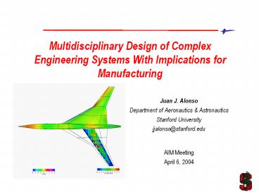
Multidisciplinary Design of Complex Engineering Systems With Implications for Manufacturing
Description:
Wing twist, camber and detailed shape (Hicks-Henne) bumps. Fuselage camber modifications ... 15 sections with modifiable shape, area, camber. Nacelles ... –
Number of Views:266
Avg rating:3.0/5.0
Title: Multidisciplinary Design of Complex Engineering Systems With Implications for Manufacturing
1
Multidisciplinary Design of Complex Engineering
Systems With Implications for Manufacturing
- Juan J. Alonso
- Department of Aeronautics Astronautics
- Stanford University
- jjalonso_at_stanford.edu
- AIM Meeting
- April 6, 2004
2
Outline
- Introduction
- The design process
- Design goals and challenges
- Our approach
- Sample Results from Current Work
- Aerodynamic shape optimization
- Aero-structural optimization
- Outlook and future work
- Treatment of the boom problem
- Manufacturing and cost observations
3
The Design Process
- Three major phases
- Conceptual market determination, rough outline
of the design - Preliminary detailed aero shape and structure,
mission, SC - Detailed actual drawings of every part in the
aircraft ready to cut - Key elements of preliminary design
- Comprehensive set of requirements / constraints
(including manufacturing) - Inputs
- Goals and objectives
- Outcome
4
Design Requirements
- Carefully formulated set of needs for the
proposed aircraft platform stated by the customer - Range, payload, speed, fuel efficiency,
performance - Weight, cost, noise, emissions
- Mission, ultimate loads / maneuver
- The more/less, the better... - Objective
functions to be maximized / minimized - Must have no less/more than... - Inequality
constraints - Must exactly satisfy... - Equality constraints
5
We Do Not Design, We Tweak
- Most transonic transports designed today are
evolutions of existing aircraft. Why? - We know how to do tube-and-wing aircraft
- Large experience database, lower risk
6
But Some Aircraft Are Not Tweaks
Bae/Aerospatiale Concorde
Lockheed SR-71 Blackbird
7
Current Preliminary Design Practices
- Conceptual design (maybe misguided) ties the
process together - Major disciplines (aerodynamics, structures) are
designed while the other one is frozen - Implicit constraints (maybe not optimal) appear
as part of the procedure (including poorly
formulated manufacturing const.) - Important trades between weight, performance,
cost are somewhat ad-hoc - This approach is not sufficient for new designs
8
Our Goals
- Simultaneously change the aerodynamic shape and
material thicknesses of the structure to achieve
a design that is best - Use sophisticated mathematical methods to achieve
reasonable turnaround - Include all relevant disciplines and constraints
to produce realistic designs - Where are we at?
9
Inputs for Preliminary Design
- Detailed list of design requirements
- Rough description of the aerodynamic shape
(Outer Mold Line - OML) - Rough description of the internal structural
layout (no details of the actual material
distribution required - just topology information)
10
Objectives for Preliminary Design
- Detailed aerodynamic shape of the configuration
- Detailed material thickness distribution
throughout the structure - Satisfy all constraints AND maximize our measure
of efficiency
11
Aircraft Design Optimization Problem
12
Optimization Approaches
13
Why Is This Challenging?
- Curse of dimensionality to properly describe the
detailed aerodynamic shape and structure of an
aircraft, hundreds of design variables are
needed. - Highly constrained problem many disciplines
impose limits on the allowed variations of the
design variables. These limits may be hard to
compute. - Brute-force methods will not work a single
high-fidelity aero-structural analysis (NS FEM)
may take several hours on multiple processors.
14
Available Approaches
- Efficient methods to obtain sensitivities of many
functions with respect to a few variables -
Direct method - Efficient methods to obtain sensitivities of a
few functions with respect to many variables -
Adjoint method - No known methods to obtain sensitivities of many
functions with respect to many design variables - This is the aircraft design problem!!!
15
What Makes Our Approach Feasible?
- Target Overnight turnaround with reasonable
large-scale computing resources 128 processors - Formulation of the adjoint problem for multiple
disciplines - Simply a sophisticated way of computing gradient
information - Two system analyses (of the aero-structural type)
provide all necessary information to compute the
full gradient vector
16
Quiet Supersonic Platform (QSP) Program
- Range 5,000 nmi
- Cruise Mach No. 1.6-1.8
- TOGW 100,000 lbs
- Initial Overpressure lt 0.3 psf
- Payload 20,000 lbs
- Swing-wing concept
Gulfstream Aerospace Corporation QSJ Configuration
17
Low Boom Supersonic Designs
- Is this combination of requirements achievable?
Can we actually do this? This is a set of
conflicting requirements the airplane may not
close - Classical sonic boom minimization theory says
that - What is the necessary aircraft length? Can we
achieve this with our target TOGW? - At Stanford we have decided to focus on
- Using aerodynamic shape optimization to take
advantage of the nonlinear interactions between
shock waves and expansions to produce shaped
booms - Using Multidisciplinary Design Optimization (MDO)
methods to minimize the weight of the airframe
18
Aero-Structural Aircraft Design Optimization
- Simultaneously change aero shape and structural
thicknesses (high-fidelity) to maximize aircraft
performance (aero and structure) while satisfying
all constraints - Compute gradients and use with gradient-based
optimizers - Achieve overnight turnaround with the use of
parallel computing
19
Outline
- Introduction
- The design process
- Design goals and challenges
- Our approach
- Sample Results from Current Work
- Aerodynamic shape optimization
- Aero-structural optimization
- Outlook and future work
- Treatment of the boom problem
- Manufacturing and cost observations
20
Aerodynamic Shape Optimization
- Minimize drag coefficient and fixed lift, M1.5
- 100,000 lbs vehicle
- 136 design variables
- Wing twist, camber and detailed shape
(Hicks-Henne) bumps - Fuselage camber modifications
- Wing and fuselage volumes are constrained not to
decrease - Wing curvature may not exceed manufacturing
constraints (provided by Raytheon aircraft) - Typically 20 design iterations (using NPSOL)
arrive at an optimum design
21
Baseline Design
- M 1.5
- C_L 0.1
- H 55,000 ft
- Axisymmetric fuselage
- Inviscid C_D 0.00858
22
Optimized Design
- M 1.5
- C_L 0.1
- H 55,000 ft
- Axisymmetric fuselage
- Inviscid C_D 0.00785
- 15 Design Iterations
23
Sample Design Problem
24
Sample Design Problem (2)
25
Sample Design Problem (3)
26
Sample Design Problem (4)
27
Sample Design Problem (5)
28
Comparison with Sequential Optimization
29
Outline
- Introduction
- The design process
- Design goals and challenges
- Our approach
- Sample Results from Current Work
- Aerodynamic shape optimization
- Aero-structural optimization
- Outlook and future work
- Treatment of the boom problem
- Manufacturing and cost observations
30
Parametric CAD Geometry Descriptions
- Complex geometry is difficult to handle during
automated design, particularly if - Complex intersections need to be computed
- Geometric level of detail is high
- Manufacturing constraints are imposed
- CAD-based design system overcomes these
limitations - Simulation directly interfaced to CAD via CAPRI
- Parametric/Master-Model concept
- Parallel/Distributed AEROSURF module for
performance
31
Aircraft Parametric Model
32
Aircraft Parametric Model
- 100 scalar parameters and 36 sections can be
controlled - Wing, fuselage, vertical and horizontal tail,
nacelles - Wing components (main wing, v- and h-tail)
- Reference area, aspect ratio, taper ratio, sweep
angle, leading and trailing edge extensions,
twist distribution (among others) - Detailed airfoil shape design at a number of
sections - Fuselage
- 15 sections with modifiable shape, area, camber
- Nacelles
- 10 parameterizations, fixed aifoil, solid of
revolution - Information returned to the simulation using
quad-patch surface grids
33
Aircraft Parametric Model Range
34
Software Integration Environments
- Neglecting the software integration challenge
will lead to failure - Aero-structural adjoint optimization approach has
over 30 well-defined modules that interact with
each other - In our ASCI project, we have chosen to explore
the use of Python to wrap Fortran 90/95, C, and
C so that everything that is available to
Python can be used by these languages - Rely on open source frameworks that add
functionality to existing code (distributed
computing, visualization, journaling, unit
conversion, etc.)
35
Pyre Distributed services
Workstation
Front end
Compute nodes
launcher
solid
monitor
fluid
journal
Michael Aivazis, Caltech
36
How About Sonic Boom?
- We have only discussed improvements to
- Aerodynamic performance
- Structural weight
- Indirect improvements in sonic boom
- How about direct impact of shaping on sonic boom?
37
How About Sonic Boom?
- Sonic boom optimization presents particularly
challenging problems because - Large mesh sizes required for accurate boom
prediction - Design space is not smooth
- Design space contains discontinuities
- Gradient-based methods do not work well in
general - Developed Genetic Algorithm based optimizations
with - Kriging and Co-Kriging response surfaces
- Gradient-enhanced Pareto front search
38
Fully Automated Sonic Boom Prediction Procedure
Fully nonlinear 3D boom prediction Driven by
parametric CAD model Unstructured mesh size 2.4
/ 3.5 million Solution from 7 min on 16 procs (
Athlon 2100xp )
Initial mesh generation Centaur
CAD parametric model AEROSURF
Mesh perturbation and regeneration Movegrid
Parallel flow solution (CFD) AirplanePlus
Near field pressure extraction Boom
prediction PCBOOM
39
Initial Unstructured Mesh Generation
Initial surface triangular mesh
Initial pressure distribution
40
Solution Adapted Meshes (3 Cycles)
41
High-Fidelity Multi-Disciplinary Optimization
- Additional disciplines needed to constrain change
in aero shape - High-fidelity trade-offs important for low-boom
supersonic aircraft
- GA needed for simultaneous boom and Cd
optimization - Non-dominated solutions form Pareto front
- Different compromises achieved
42
Design Space Exploration
43
Inside a Hard Disk Drive
44
MDO for Launch Vehicles
- Why MDO for launch vehicles?
- Cost Current U.S. LVs 40,000 / kg to LEO
small improvements yield big rewards. - Performance Payload mass to orbit depends
exponentially on many vehicle parameters - Coupled Environments Wide-ranging aerodynamic,
thermal, and structural loading tightly coupled
45
Conclusions Future Work
- High-fidelity design becoming a reality
- Much work remains in making it truly useful
- Manufacturing constraints and cost modeling are
not a major part of the process - Plenty of opportunities to streamline / optimize
the complete process, not just the performance of
the vehicles
46
(No Transcript)
Recommended
CrystalGraphics Presentations


