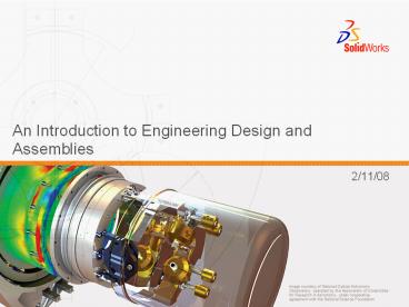
An Introduction to Engineering Design and Assemblies - PowerPoint PPT Presentation
Title:
An Introduction to Engineering Design and Assemblies
Description:
Image courtesy of National Optical Astronomy Observatory, operated by the ... mate between the flat cut face of the fastener and the flat top face of the switchplate. ... – PowerPoint PPT presentation
Number of Views:192
Avg rating:3.0/5.0
Title: An Introduction to Engineering Design and Assemblies
1
An Introduction to Engineering Design and
Assemblies
- 2/11/08
2
Features
1.Base Extrude
2.Fillets
3.Shell
3
Assembly Basics
- An assembly contains two or more parts.
- In an assembly, parts are referred to as
components. - Mates are relationships that align and fit
components together in an assembly. - Components and their assembly are directly
related through file linking. - Changes in the components affect the assembly.
- Changes in the assembly affect the components.
4
Assembly Basics
- The first component placed into an assembly is
fixed. - A fixed component cannot move.
- If you want to move a fixed component, you must
Float (unfix) it first. - Tutor1 is added to the FeatureManager design tree
with the symbol (f). - The symbol (f) indicates a fixed component.
5
Assembly Basics
- Tutor2 is added to the FeatureManager design
tree with the symbol (-). - The symbol (-) indicates an underdefined
component. - Tutor2 is free to move and rotate.
6
Manipulating Components
- Move components by dragging.
- Move components with a triad.
- Move Component translates (moves) the
selected component according to its available
degrees of freedom.
7
Manipulating Components
- Rotate components by dragging.
- Rotate components with a triad.
- Rotate Component rotates the selected
component according to its available degrees of
freedom.
8
Degrees of Freedom There are Six
- They describe how an object is free to move.
- Translation (movement) along X, Y, and Z axes.
- Rotation around X, Y, and Z axes.
9
Mate Relationships
- Mates relationships align and fit together
components in an assembly. - The Tutor assembly requires three mates to fully
define it. The three mates are - Coincident between the top back edge of Tutor1
and the edge of the lip on Tutor2.
10
Mate Relationships
- Second Mate Coincident mate between the right
face of Tutor1 and the right face of Tutor2. - Third Mate Coincident mate between the top face
of Tutor1 and the top face of Tutor2.
11
Mates and Degrees of Freedom
- The first mate removes all but two degrees of
freedom. - The remaining degrees of freedom are
- Movement along the edge.
- Rotation around the edge.
12
Mates and Degrees of Freedom
- The second mate removes one more degree of
freedom. - The remaining degree of freedom is
- Rotation around the edge.
13
Mates and Degrees of Freedom
- The third mate removes last degree of freedom.
- No remaining degrees of freedom.
- The assembly is fully defined.
14
Additional Mate Relationships Example
- The switchplate requires two fasteners.
- Create the fastener.
- Create the switchplate-fastener assembly.
15
Additional Mate Relationships
- The switchplate-fastener assembly requires three
mates to be fully defined. The three mates are - First Mate Concentric mate between the
cylindrical face of the fastener and the
cylindrical face of the switchplate.
16
Additional Mate Relationships
- Second Mate Coincident mate between the flat
circular back face of the fastener and the flat
front face of the switchplate.
17
Additional Mate Relationships
- Third Mate Parallel mate between the flat cut
face of the fastener and the flat top face of the
switchplate. - The switchplate-fastener assembly is fully
defined.
18
Additional Mate Relationships
- The cdcase-storagebox assembly requires three
mates to be fully defined. The three mates are - First Mate Coincident between the inside
bottom face of the storagebox and the bottom
face of the cdcase.
19
Additional Mate Relationships
- Second Mate Coincident mate between the inside
back face of the storagebox and the back face
of the cdcase.
20
Additional Mate Relationships
- Third Mate Distance mate between the inside
left face of the storagebox and the left face of
the cdcase. - Distance 1cm.

